Liquid level controller

Inactive Publication Date: 2005-06-28
CAZDEN MICHAEL L
View PDF7 Cites 24 Cited by
  • Summary
  • Abstract
  • Description
  • Claims
  • Application Information

AI Technical Summary

Benefits of technology

[0013]The liquid level controller of the present invention generally comprises a transmitter unit that is placed in the liquid container or pool. The transmitter includes a vertically movable float member, slidably inserted into a float chamber, said float member buoyantly responsive to changes in the liquid level in the container and having means for closing an electronic switch when the liquid level buoys the float to a predetermined height within the transmitter unit. When the switch is closed, the transmitter sends a radio frequency signal to a remotely located receiving unit operatively coupled to a liquid supply valve. The receiver, in turn, activates means to open the valve and permit the flow of additional liquid into the pool. Once the desired level is reached, the transmitter unit sends a second signal to the receiver to close the valve and shut off the supply of water. The transmitter unit, moreover, includes programmable logic means for distinguishing between transitory liquid level fluctuations, caused by splashing, wind induced wave actions, and other kinds of wa

Problems solved by technology

Liquid level variations are particularly problematic when a large surface area of the liquid is exposed to the atmosphere, resulting in large liquid losses due evaporation.
This is especially problematic in swimming pools, which also suffer large water volume losses due to splashing.
The reliable control of water level in a swimming pool is imperative for a number of reasons: firstly, pool filters can malfunction if the water level falls too low; secondly, damage to pool surfaces and sidewalls may result from exposure due to low water; thirdly, the chemical balance of swimming pool water depends on tight control of the chemical composition, and this balance is undermined by the addition or removal of large volumes of water, resulting in decreased microbicidal effectiveness and/or discomfort to swimmers due to high chemical concentrations.
As a practical matter, deviations from an optimum water level may not be noticed until the d

Method used


Image

  • Liquid level controller
  • Liquid level controller
  • Liquid level controller

Examples


Embodiment Construction

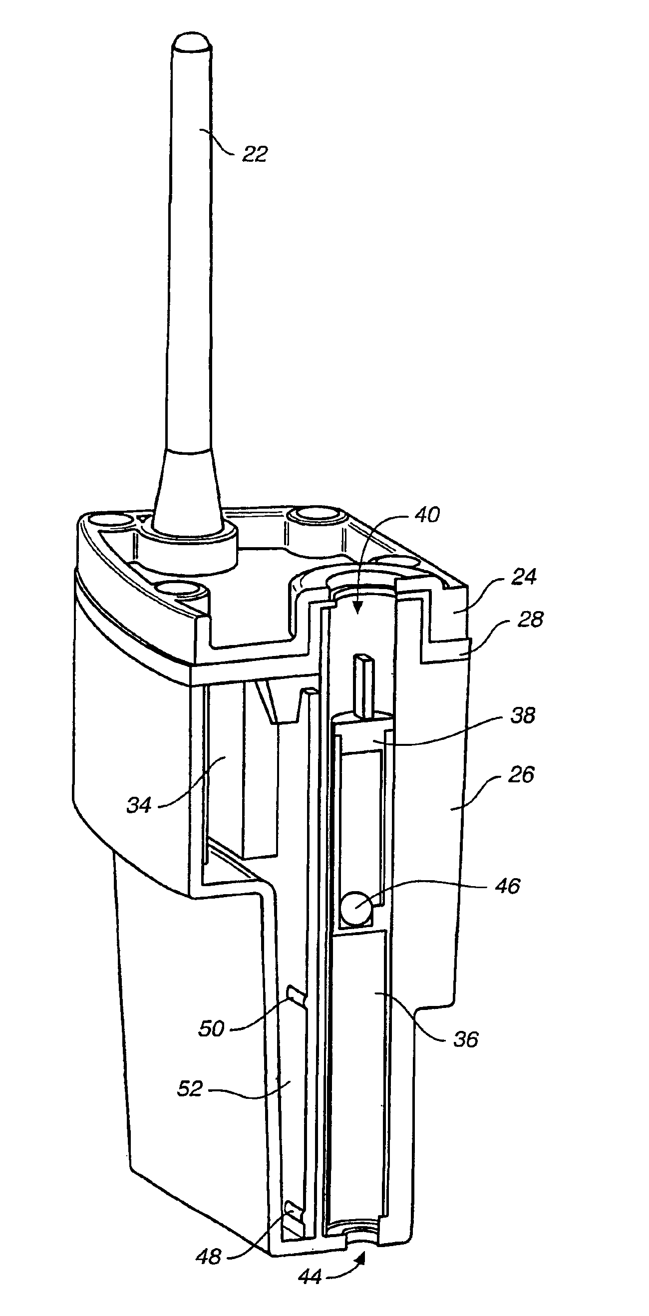
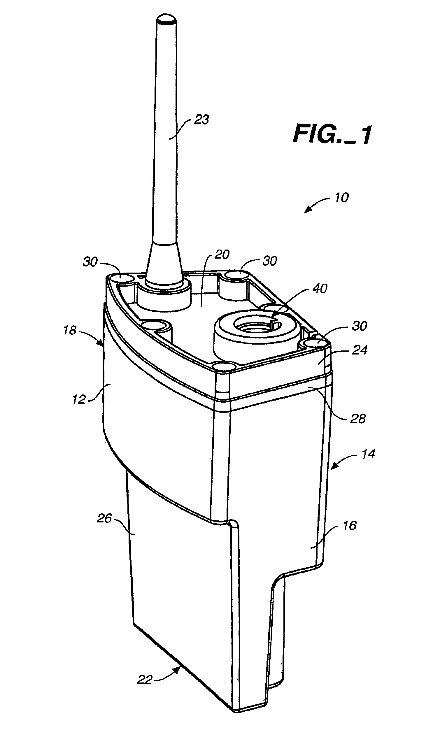
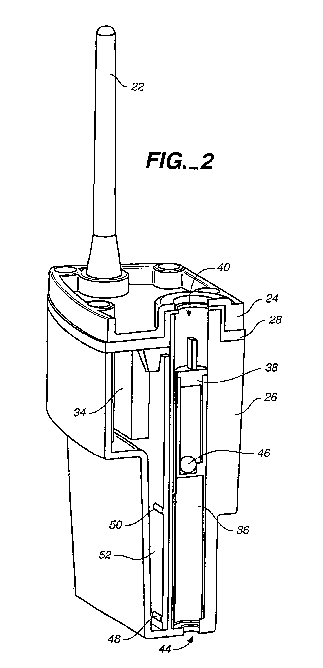
[0028]FIGS. 1 through: 4 provide various views of the transmitter unit of the liquid level controller of the present invention. FIG. 1 is a perspective view in elevation of the transmitter unit, and FIG. 2 is a cross-sectional perspective view thereof FIG. 2A is a cross-sectional side view in elevation of the transmitter of FIGS. 1 and 2, showing the position of the buoyant float at the high water level range of motion, while FIG. 2B is a cross-sectional side view in elevation of the transmitter showing the float member at the low water level range of motion. Finally, FIG. 3 is a top perspective view of the transmitter unit of FIGS. 1 and 2, showing the cylindrical float member inserted in the float chamber, and FIG. 4 is a perspective view in elevation of an alternative embodiment of the transmitter unit, showing the cylindrical float member emerged from, but aligned with, the float chamber. These views collectively show that the transmitter unit comprises a housing, generally deno...


PUM


Abstract

A liquid level control system for detecting and responding to changes in the level of liquid in a container. The system includes a transmitter in radio communication with a receiver, which is in turn connected to a valve assembly. The transmitter unit is programmable to respond to changes in the level of liquid in a container and to emit a radio signal receivable by the receiver unit, which controls the release of liquid to the liquid container via the valve assembly. The signal may be suppressed by a timing circuit in the transmitter circuitry unless and until a liquid level change is sufficiently sustained. The receiver is also programmable to keep the liquid control valve open a predetermined amount of time or to close the valve upon receipt of a high liquid level signal.

Description

[0001]This application claims the benefit of provisional application No. 60,245,005, filed Oct. 30, 2000.BACKGROUND OF THE INVENTION[0002]1. Technical Field[0003]The present invention relates generally to liquid level controllers, and more particularly to an automatic liquid level control system having a remote sensor for sensing the liquid level in a container, wherein the sensor is in communication with an electronically activated control valve that regulates the fill level in the liquid container.[0004]2. Background Art[0005]Maintaining a constant volume of liquid in a container is important in several industrial and non-industrial arenas. Liquid level variations are particularly problematic when a large surface area of the liquid is exposed to the atmosphere, resulting in large liquid losses due evaporation. This is especially problematic in swimming pools, which also suffer large water volume losses due to splashing.[0006]The reliable control of water level in a swimming pool i...

Claims


Application Information

Patent Timeline
IPC IPC(8): E04H4/12E04H4/00F16K33/00G01F23/30G01F23/74G01F23/00G01F23/70G05D9/12
CPCE04H4/12F16K33/00G05D9/12G01F23/70G01F23/74G01F23/0084Y10T137/7306Y10T137/7287G01F23/806
Inventor CAZDEN, MICHAEL L.
Owner CAZDEN MICHAEL L
Why Eureka
Try Eureka