Shock mount assembly with polymeric thimble tube

a technology of shock mount and thimble tube, which is applied in the direction of machine supports, transportation and packaging, and other domestic objects, can solve the problems of increasing product cost, not being able to meet the requirements of strength variation, and suffering from a disadvantage of its own, so as to achieve the effect of reducing manufacturing failures and reducing manufacturing costs

Inactive Publication Date: 2005-06-28
ILLINOIS TOOL WORKS INC
View PDF22 Cites 83 Cited by
  • Summary
  • Abstract
  • Description
  • Claims
  • Application Information

AI Technical Summary

Benefits of technology

[0008]Another object of the present invention is to provide a shock mount assembly having the above characteristics and which has a lower cost of manufacture than known designs.
[0009]A further object of the present invention is to provide a shock mount assembly having the above characteristics and which has a lower incidence of manufacturing failures than known designs.

Problems solved by technology

While this known shock mount is exceptionally effective and has high strength characteristics, it does not allow for variations in strength requirements.
In such case, each shock mount must be separately designed and manufactured, increasing product cost.
While this shock mount design provides excellent results, it suffers from a disadvantage of its own.
This arrangement requires the manufacture of an additional piece, which consequently adds to the cost of manufacturing the shock mount.
Moreover, the provision of inward protrusion may lead to an increased incidence of manufacturing failures, as when the thimble stem is inserted into the spacer tube, one or more of the protrusions may not bend inwardly properly, resulting in a skewed or failed insertion.
Furthermore, even if the thimble stem appears to have been inserted properly, the inward protrusions may not properly engage the lip on the thimble stem, thereby lowering the retention force.

Method used


Image

  • Shock mount assembly with polymeric thimble tube
  • Shock mount assembly with polymeric thimble tube
  • Shock mount assembly with polymeric thimble tube

Examples


Embodiment Construction

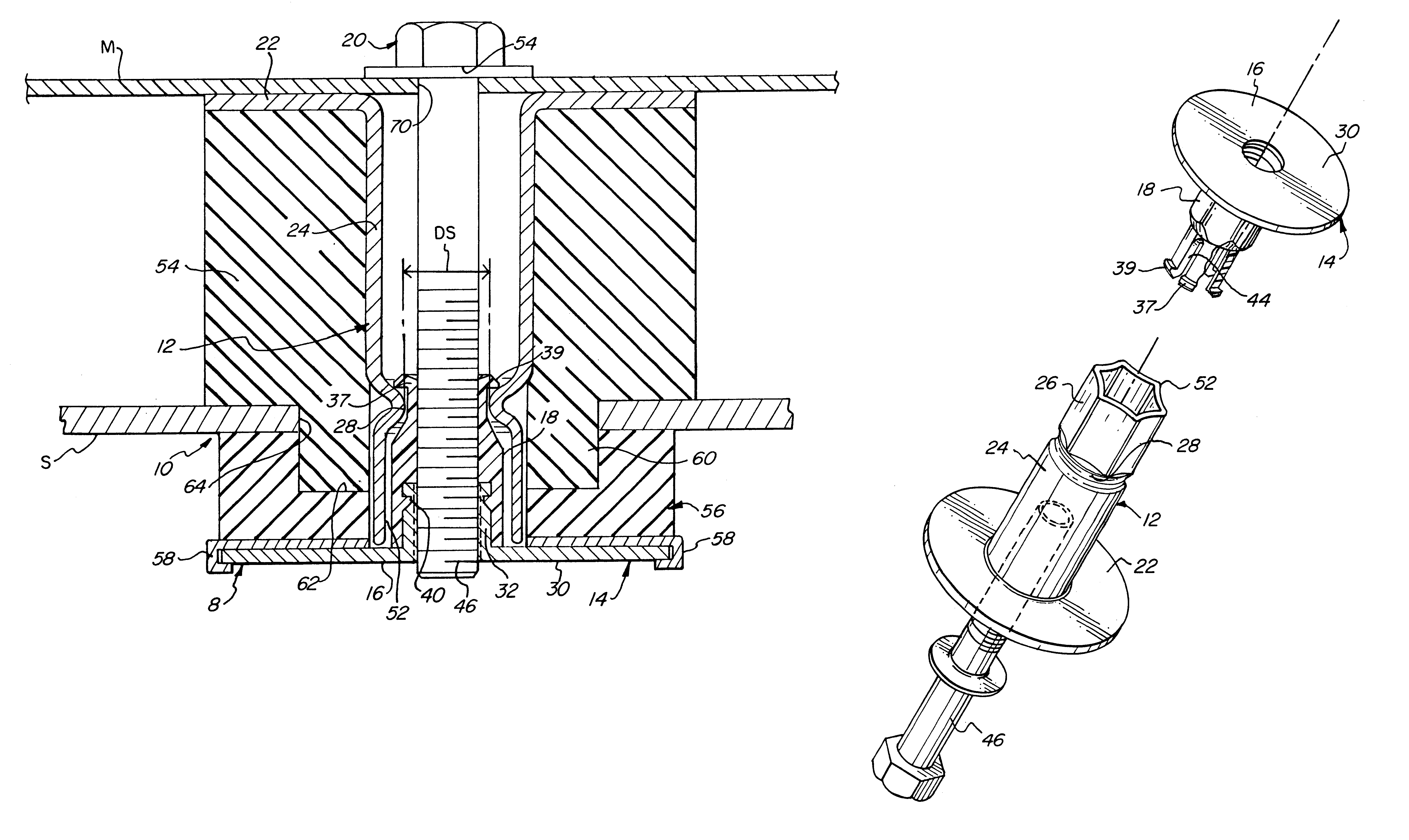
[0032]Referring first to FIGS. 1-8, wherein like numerals indicate like elements in the drawings, an improved shock isolating mount 10 in accordance with one embodiment of the invention is shown. Shock isolating mount 10 (also referred to herein as a “shock mount”) comprises a spacer 12 and a thimble 14. Thimble 14 comprises a base 16 and a stem 18. A fastener 20 is provided to secure together the shock mount 10.

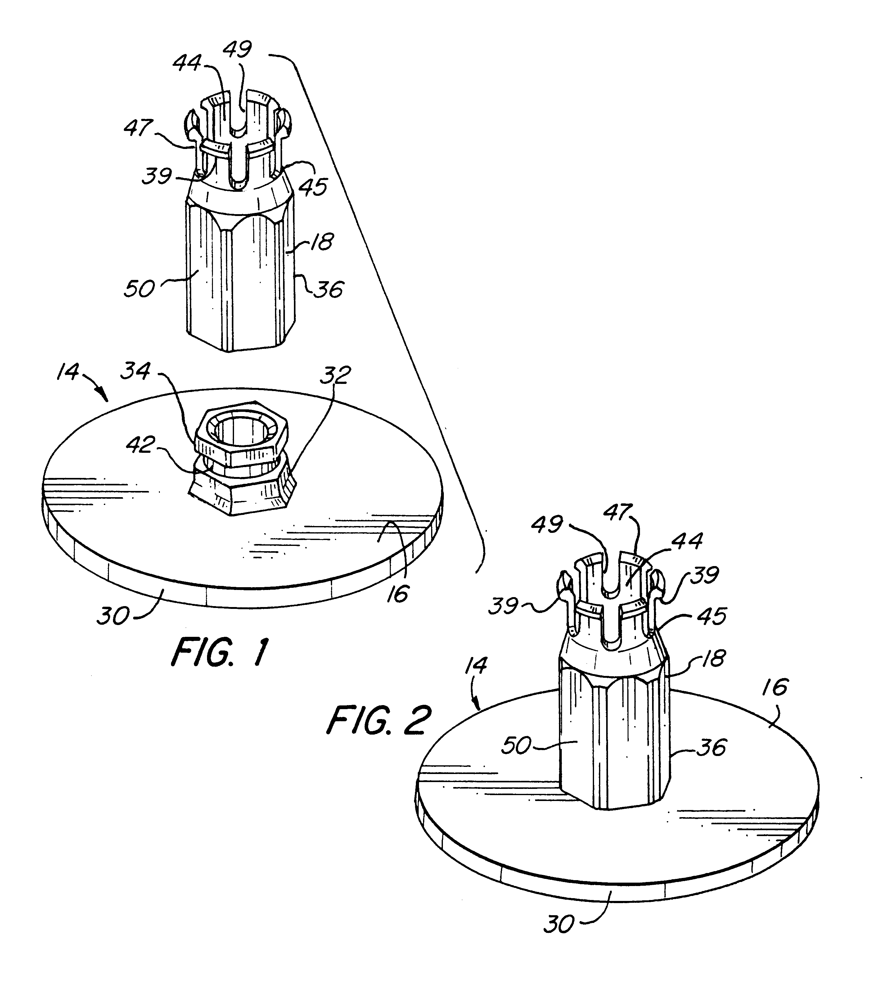
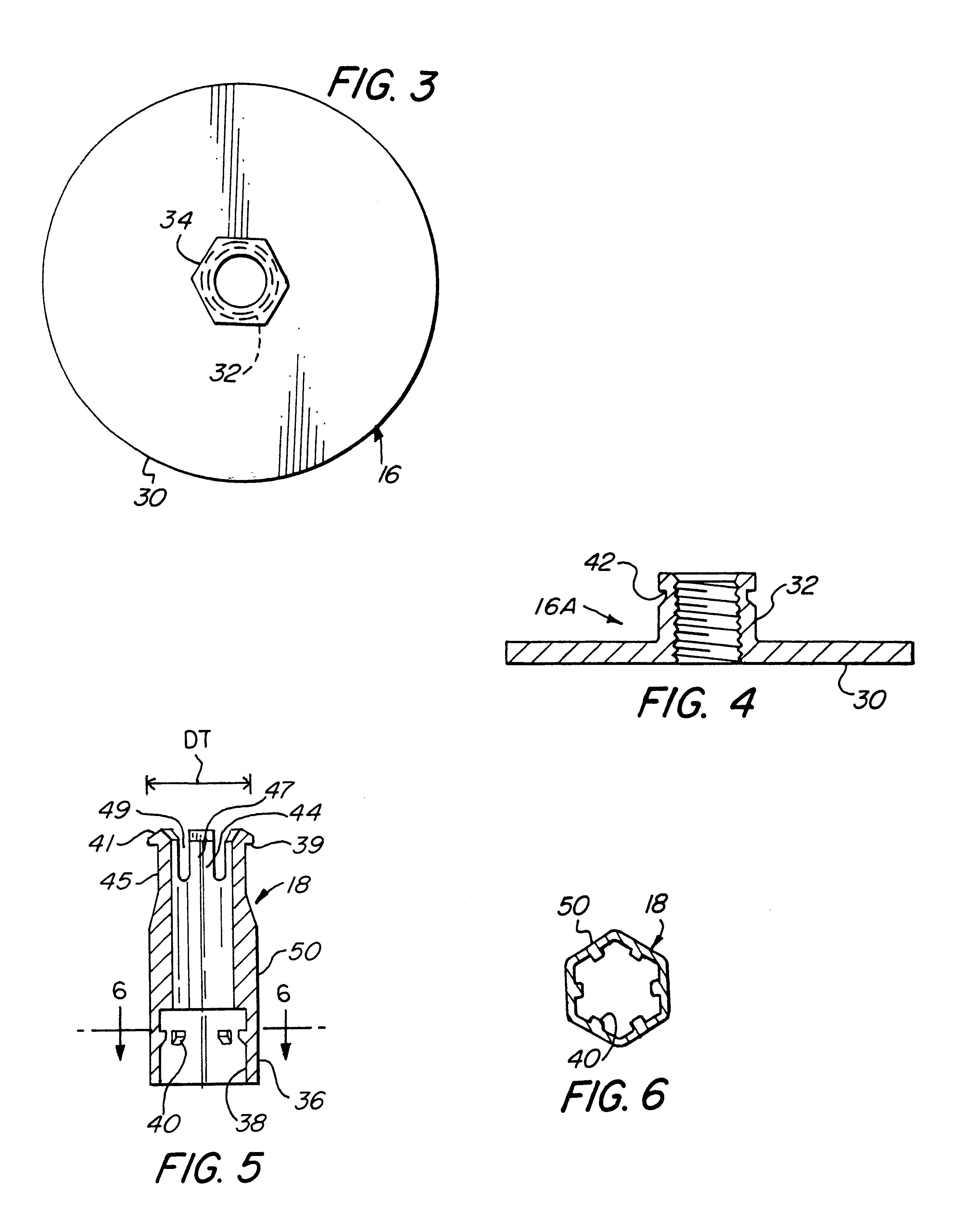
[0033]The base 16 of thimble 14 is a metal part having an annular flange 30 and an internally threaded post 32 integrally formed with and projecting from flange 30. In this embodiment, the outer wall 34 of post 32 is non-circular in cross-section; preferably outer wall 34 is hexagonal in cross-section.

[0034]Stem 18 is a plastic part, preferably formed from a thermoplastic polymer. Stem 18 is hollow, and has a lower portion 36 that, in this embodiment, has an inner wall 38 with a non-circular cross-section, preferably a hexagonal cross-section. Lower portion 36 of stem 18 rec...


PUM


Abstract

A shock mount assembly is provided, which generally includes a spacer and a thimble. The spacer includes a spacer flange and a spacer tube projecting from the spacer flange. The spacer tube includes an inwardly projecting shoulder having an inner diameter. The thimble includes a metal thimble base having a flange and an internally threaded post projecting from the flange. The threaded post has at least one hole passing through a wall thereof. The thimble also includes a plastic hollow thimble stem. The stem includes at least one hole passing through a wall of the lower portion thereof, the hole having a leg extending inwardly from one of the walls thereof. The leg includes a radially inwardly extending tab sized, shaped and positioned to engage the hole passing through the wall of the threaded post in a snap fitted arrangement when the threaded post is inserted into the stem. The stem also includes projecting from a top end thereof a plurality of fingers spaced about a periphery thereof. Each of the fingers has an outwardly projecting portion defining a circumferential lip having an outer diameter larger than the inner diameter of the shoulder of the spacer tube of said spacer. The stem is telescopically receivable in the spacer tube such that when the stem is fully inserted in the spacer tube, the lip engages the shoulder in a snap fitted

Description

FIELD OF THE INVENTION[0001]The present invention relates to an improved shock mount assembly for securing a heavy structure, such as a vehicle body, to a support, such as the frame of a vehicle, and absorbing vibrations or shocks between the two structures.BACKGROUND OF THE INVENTION[0002]A shock mount currently used in the automotive industry to secure truck bodies to truck frames is disclosed in U.S. Pat. Nos. 4,783,039 and 4,720,075 to Peterson et al., the disclosures of which are hereby incorporated by reference. This shock mount has been successful in the industry due to its design features which provide a telescoping metal spacer and metal thimble assembly that snap together to hold the thimble and spacer together until secured with a threaded fastener, and in which the thimble and spacer have mating surfaces to prevent either one from rotating relative to the other, thereby permitting fastening of the threaded fastener with minimal undesirable rotation of one element relativ...

Claims


Application Information

Patent Timeline
Patent Type & Authority Patents(United States)
IPC IPC(8): B62D24/00B62D24/02F16F1/373
CPCF16F1/3735B62D24/02
Inventor NORKUS, JAMESBUGNACKI, RANDY MICHAEL
Owner ILLINOIS TOOL WORKS INC
Why Eureka
Try Eureka