Liquid discharge recording head cartridge and liquid discharge recording apparatus

a liquid discharge recording and recording head technology, applied in printing and other directions, can solve the problems of insufficient sealing amount control, insufficient sealing amount of coating, and insufficient sealing, etc., to enhance the relative positional precision of the upper face, improve the coupling reliability, and improve the effect of precision

Inactive Publication Date: 2005-06-28
CANON KK
View PDF13 Cites 24 Cited by
  • Summary
  • Abstract
  • Description
  • Claims
  • Application Information

AI Technical Summary

Benefits of technology

[0021]Also, if the screw retaining boss is installed on one and the same member forming the portion having the liquid inlet ports opened thereto, it becomes possible to enhance the relative positional precision of the upper faces of the screw retaining portion and the portion having the liquid inlet ports opened thereto, thus enabling the first plate to abut against the portion to which the liquid supply paths are open in good precision to apply an appropriate contact pressure. The coupling reliability is enhanced more if the liquid supply unit and the first plate are bonded by use of adhesive agent in addition to the use of screws for coupling.
[0022]If the liquid supply unit portion and the recording element unit are adhesively bonded to each other for coupling on the bonding face portion other than the location where the elastic sealing member is arranged under pressure, there is no need for the application of adhesive agent between the one end portion of the liquid supply path of the recording element unit and the communicating passage of the liquid supply unit. As a result, it becomes unnecessary to control the coating amount of adhesive agent rigidly, thus making the assembling of a recording head faster and easier.
[0023]When an adhesive agent is filled in a space formed by the elastic member, the second base plate, and the outer circumference of the flow paths of the flow path formation member, the communicating portion is sealed from the outside both by the elastic member and the adhesive agent, and the sealing strength is enhanced. Thus, it becomes possible to prevent ink from leaking from the contact portion of the second base plate and the outer circumference of the flow paths of the flow path formation member or to prevent the air from entering the flow paths from such contact portion. Also, with the aforesaid space being filled in by the adhesive agent, only the adhesive agent is in contact with ink even if there is an ink leakage from the contact portion. There is no possibility that ink is directly in contact with the elastic member. As a result, it becomes possible to prevent discharge defects due to oil or other impurities adhering to the elastic member or to prevent ink from being condensed by the partial elution of the elastic member into the ink flow paths. In this way, the reliability of an ink jet recording head can be enhanced, while the recording quality is improved by the stabilized ink bubbling.
[0024]With the sealing member having a plurality of sealing portions planted in circular each with flat and smooth surface on the mat portion having satin surface, it becomes possible to prevent sealing members from sticking to each other when a number of them are handled. Thus, the handling thereof is made easier. Also, there is no need for using material having a large hardness as in the conventional art. It is still possible to secure a good sealing capability by use of a soft material.
[0025]Here, if the center line average roughness of the satin surface of the mat portion is kept within a range of 10 to 50 μm, the sealing members can be prevented from sticking to each other assuredly. If the center line average roughness of the flat and smooth surface of the sealing portion is set at 10 μm or less, a good sealing capability can be secured. When the sealing member is formed by chlorinated butyl rubber having hardness (JIS A) within a range of 30 to 50, it becomes possible to secured the reliability of the sealing member for a long time.
[0026]For the liquid discharge recording head carriage of the invention or the image forming apparatus, if the center line average roughness of the portion abutting against the liquid tank connection portion and the sealing portions of the sealing member of the liquid discharge head is set at 0.5 μm or less or if a smoothing layer is formed for the abutting portion of the liquid tank connecting portion and the sealing portions of the sealing member of the liquid discharge head for smoothing the surface thereof, it becomes possible to secure a good sealing capability between the liquid tank connecting portion and the liquid discharge head.

Problems solved by technology

With the coupling method that utilizes the sealant for sealing when coupling the ink supply paths of the recording head unit and the flow path formation member of the holder portion, the sealing strength between sealant and resin material is not sufficient enough so that the air is allowed to be accumulated in the ink jet recording head to block the ink supply into the discharge ports in some cases, and causes the “ink deficiency”.
Also, it is difficult to control the coating amount of sealant appropriately.
Should the amount thereof be slightly short, there is no problem in the initial stage, but when the air accumulation is created in the ink jet recording head, it brings about the “ink deficiency” in some cases.

Method used


Image

  • Liquid discharge recording head cartridge and liquid discharge recording apparatus
  • Liquid discharge recording head cartridge and liquid discharge recording apparatus
  • Liquid discharge recording head cartridge and liquid discharge recording apparatus

Examples


embodiment 1-1

(Embodiment 1-1)

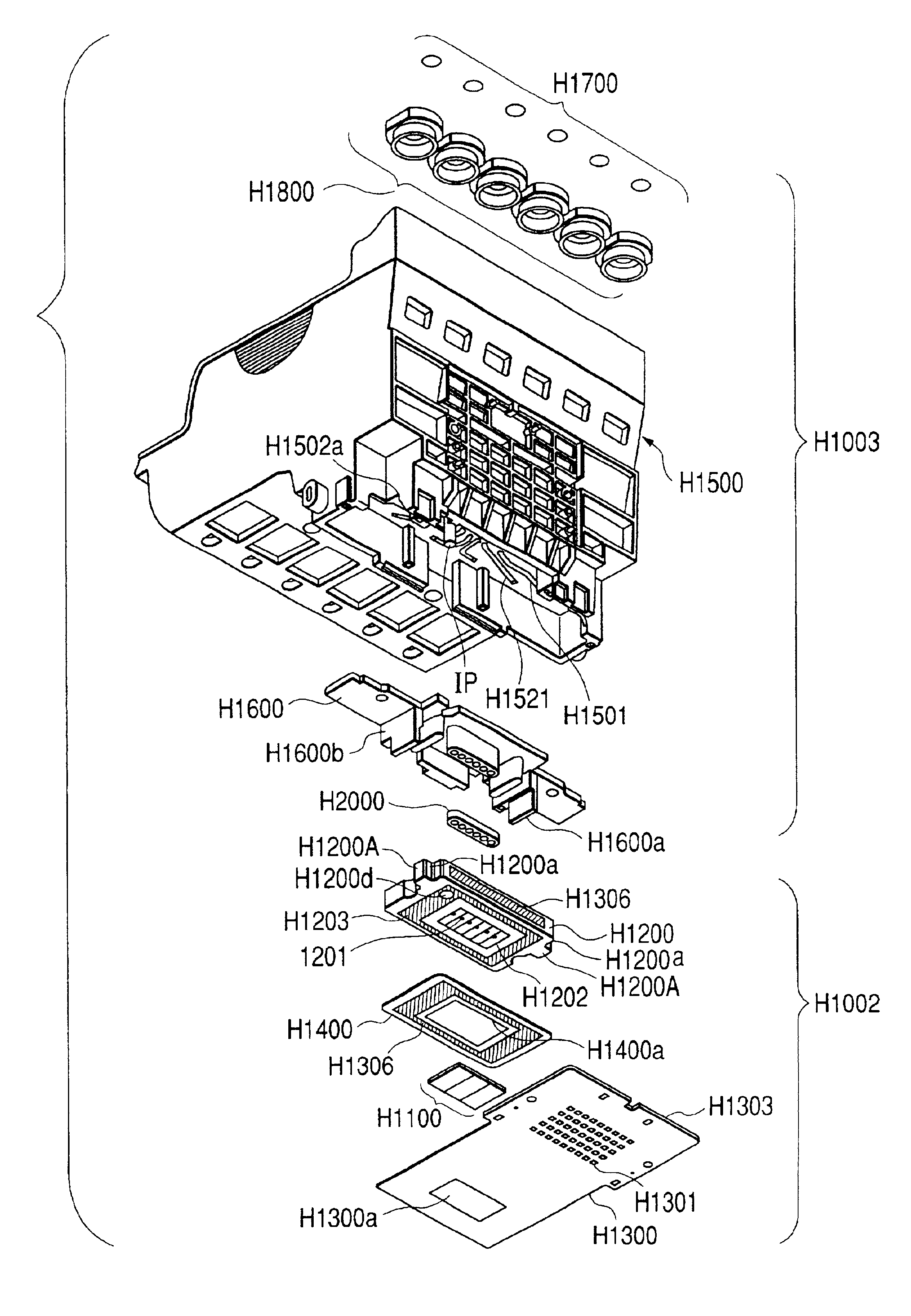
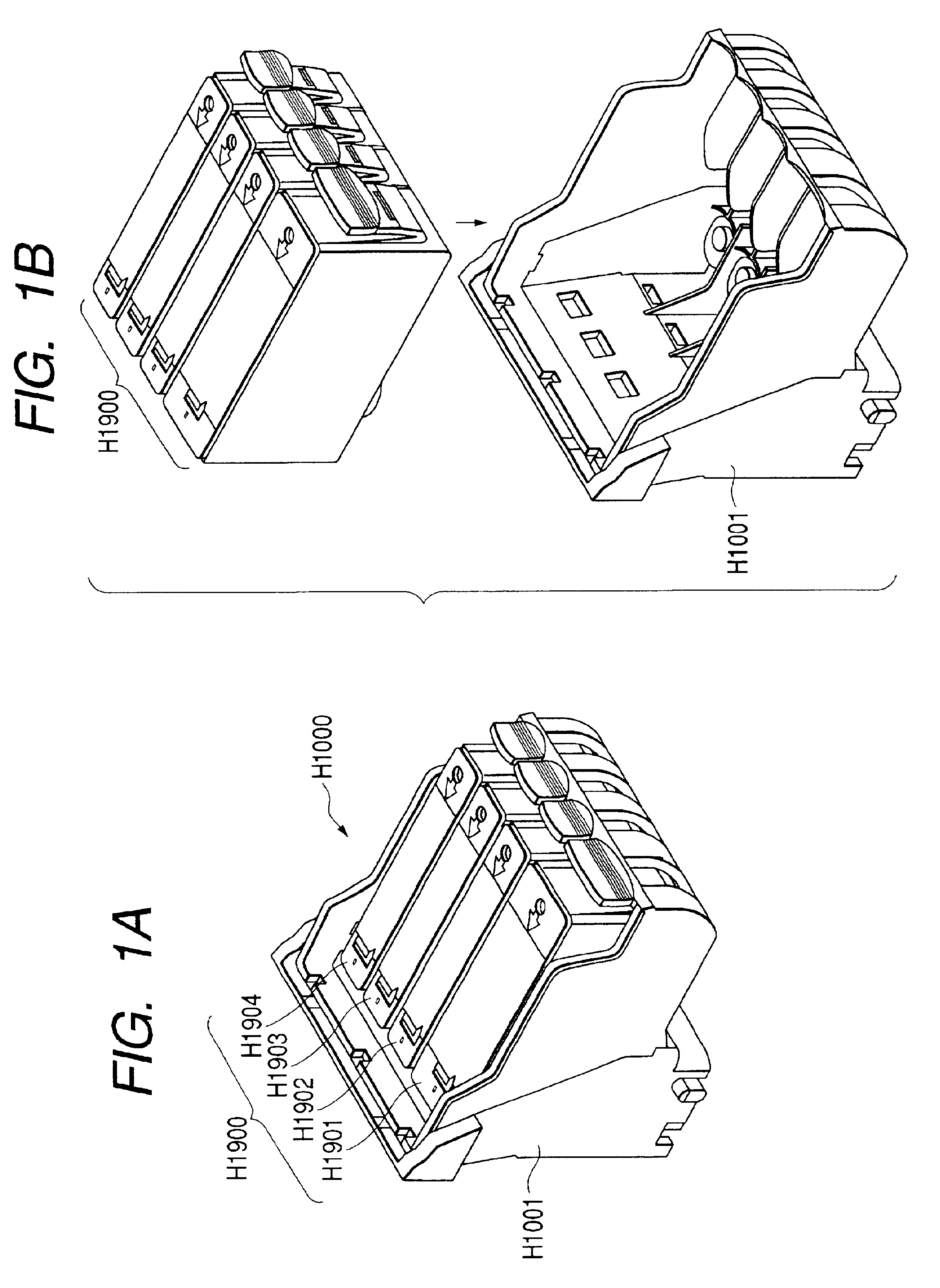
[0064]FIGS. 1A and 1B to FIG. 10 are views which illustrate the recording head cartridge (liquid discharge recording head cartridge) embodying the present invention or to which the present invention is preferably applicable, and the recording head unit and the ink tank portion that retains ink (liquid), respectively, for the cartridge, as well as the respective relations between them. Hereunder, with reference to these figures, each of the constituents will be described.

[0065]As understandable from the perspective views of FIGS. 1A and 1B, the recording head unit H1001 of the present invention is one constituent that forms a recording head cartridge H1000. The recording head cartridge H1000 is formed by the recording head unit H1001 and the ink tank H1900 which is detachably attachable thereto. The recording head cartridge H1000 is positioned by positioning means to the carriage (not shown) of the ink jet recording apparatus main body, and mounted to be electrically ...

embodiment 1-2

(Embodiment 1-2)

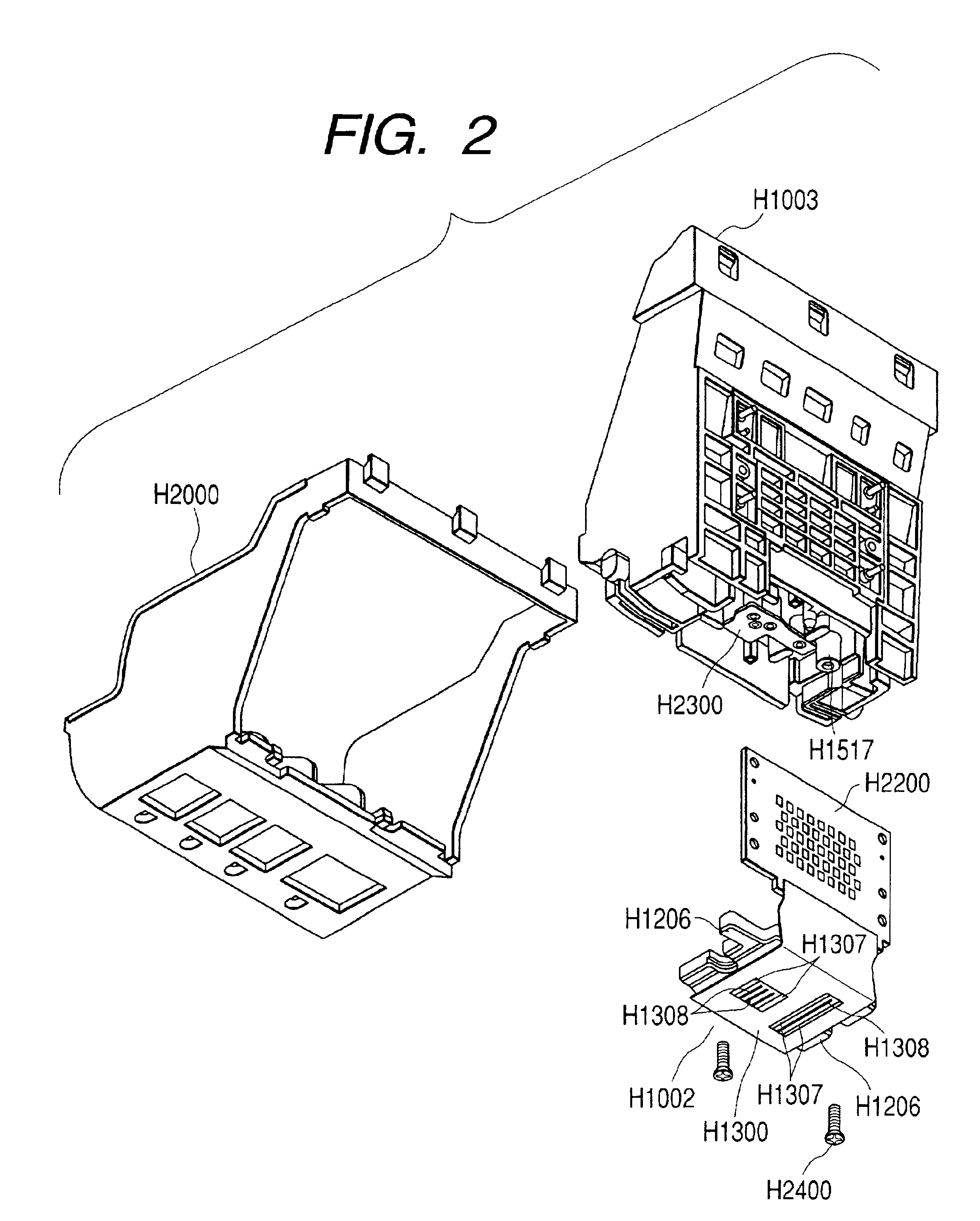
[0100]Next, with reference to FIGS. 11A and 11B and FIGS. 12A and 12B, the description will be made of the embodiment 1-2 in accordance with the present invention. The present embodiment is the variational example of the screw retaining boss H1517 of the screw H2400 for coupling and fixing the recording element unit H1002 and ink supply unit H1003 provided for the recording head cartridge H1000 of the ink supply unit H1003 of the embodiment 1-1. FIGS. 11A and 11B and FIGS. 12A and 12B illustrate the flow path formation member H1600B which is the structural component of the ink supply unit H1003 of the recording head cartridge H1000 in order to represent the characteristics of the modified portion. Any other parts are the same as those of the embodiment 1-1, and the description thereof will be omitted.

[0101]Whereas the screw retaining boss H1517 is provided for the ink supply member H1500 of the ink supply unit H1003 in the embodiment 1-1, the screw retaining boss H16...

embodiment 1-3

(Embodiment 1-3)

[0106]Next, with reference to FIG. 13, the embodiment 1-3 will be described in accordance with the present invention. FIG. 13 is an exploded perspective view which shows a recording head cartridge H1000C of the present embodiment. In FIG. 13, the same reference marks are applied to the same parts as those appearing in the embodiment 1-1, and the description thereof will be omitted.

[0107]For the present embodiment, the recording element unit H1002 and the ink supply unit H1003C are fixed by the application of adhesive agent in addition to the use of the screws H2400. As shown in FIG. 13, for the ink supply unit H1003C of the present embodiment, an adhesive agent coating portion H1518 is formed for the ink supply member H1500, and also, an adhesive agent coating portion H1605 is formed for the liquid flow formation member H1600. The recording element unit H1002 and the ink supply unit H1003 are adhesively bonded by applying RTV silicone adhesive agent, the epoxy adhesi...


PUM


Abstract

A liquid discharge head cartridge includes a recording element unit having a plate member with liquid supply paths for supplying liquid to a recording element base plate for recording by discharging the liquid; a liquid supply unit portion having a communication passage for conducting liquid from a liquid supply source; and an elastic sealing member that forms a seal between one end portion of the liquid supply paths of the plate member and an end portion of the communication passage facing the one end portion of the liquid supply paths. The elastic sealing member is provided with liquid flow paths communicating with the liquid supply paths and the communication passage. The liquid supply unit portion and the recording element unit are adhesively bonded with each other at locations other than those having the elastic sealing member arranged thereon.

Description

BACKGROUND OF THE INVENTION[0001]1. Field of the Invention[0002]The present invention relates to a liquid discharge recording head cartridge and a liquid discharge recording apparatus. The invention is not only applicable to the general recording apparatus, but also, to a copying machine, a facsimile apparatus provided with communication system, a word processor provided with a recording unit, or the like, as well as to a recording apparatus for industrial use which is complexly combined with various processing devices.[0003]The term “printing” referred to in the description of the specification hereof is meant to include the formation of characters, graphics, and the other meaningful information, and also, include broadly images, figures, patterns, and others which are formed on a printing medium, and the processing of a printing medium as well, irrespective of whether such formation is meaningful or meaningless, and also, whether or not, apparent so as to be visually recognizable ...

Claims


Application Information

Patent Timeline
Patent Type & Authority Patents(United States)
IPC IPC(8): B41J2/175
CPCB41J2/17523B41J2/17553B41J2002/14362B41J2/175
Inventor KAWAMURA, SHOGOHIROSAWA, TOSHIAKINOZAWA, MINORUMIYAZAKI, KYOTAUDAGAWA, KENTAIWANAGA, SHUZOOKITO, KAZUHIKO
Owner CANON KK
Why Eureka
Try Eureka