Traffic flow and route selection display system for routing vehicles

a display system and traffic flow technology, applied in the field of traffic information display system, can solve the problems of not providing in any form, and none of the existing road and traffic reporting/display systems are known to provide real-time displays of current traffic conditions, so as to facilitate the display of appropriate possible routes

Inactive Publication Date: 2005-06-28
CHEN SHAWFU
View PDF4 Cites 120 Cited by
  • Summary
  • Abstract
  • Description
  • Claims
  • Application Information

AI Technical Summary

Benefits of technology

[0014]Yet another and further object of the invention is the provision of a real-time traffic reporting and display system that employs color-coding to identify traffic speed conditions, and permits users to associate frequently used destinations with predetermined selection signal devices such as dedicated push buttons, so as to facilitate the display of appropriate possible routes to those destinations.

Problems solved by technology

However, none of the existing road and traffic reporting / display systems are known to provide real-time displays of current traffic conditions along selected and alternative routes in an area surrounding a vehicle.
And further, existing systems are not known to provide in any form, for identifying alternate routes that are preferable based upon comparative traffic speed conditions and / or travel time to a given destination.

Method used


Image

  • Traffic flow and route selection display system for routing vehicles
  • Traffic flow and route selection display system for routing vehicles
  • Traffic flow and route selection display system for routing vehicles

Examples


Embodiment Construction

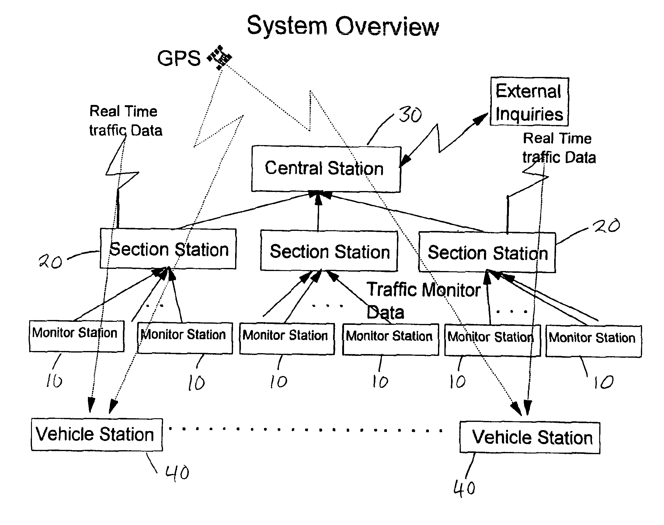
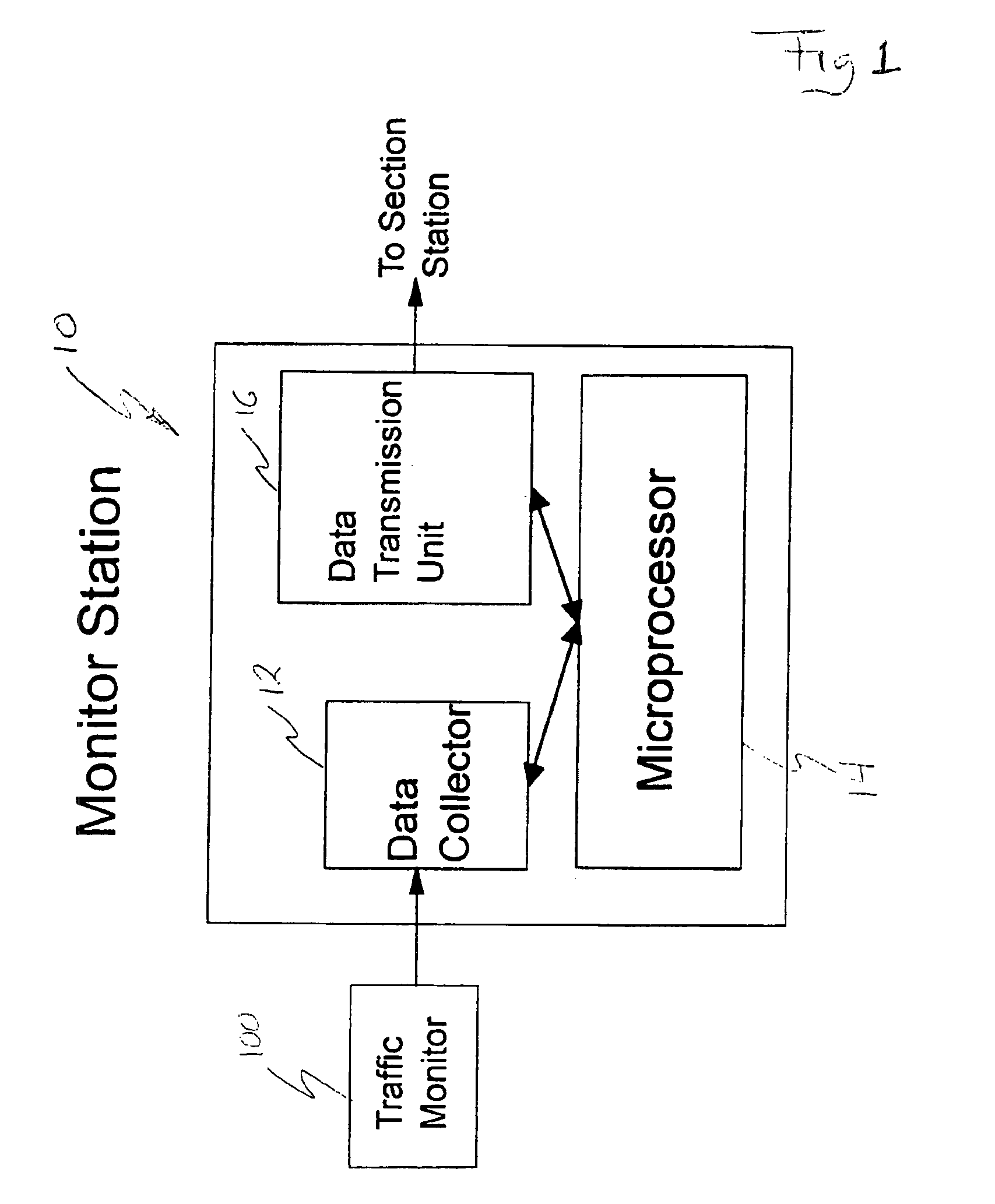
[0032]Referring now to the drawings, a monitor station 10 in accordance with this invention, as shown in FIG. 1 may be seen to comprise a data collection device 12 of any suitable well-known design for receiving electronic traffic speed signals from a traffic monitoring sensor or transducer 18, which also may be of any suitable type. The collection device 12 is connected to a microprocessor 14 capable of storing signals received by the collection device 12 and processing those signals to create data signals representative of the speed of traffic passing the monitor station 10.

[0033]It should be understood readily by those skilled in the related art, that any of the signals referred to herein may be either analog or digital or, if desired, a combination thereof. In the event that a combination of such signals are used, a suitable analog / digital [A / D] converter device of readily available type may be incorporated into the system of this invention at any suitable point, to accommodate ...


PUM


Abstract

A real-time vehicular traffic flow display system employs groups of monitor stations positioned at spaced-apart locations along vehicular roadways, to sense the speed of traffic flow on a given portion of a route. Individual section stations each serve a sequential group of different monitor stations. Each monitor station senses the speed of vehicular traffic a given road portion and transmits corresponding information to an associated section station; each section station processes the received signals, and transmits them to display stations on board vehicles in addition to sending the signals to an optional geographic area central station. The signals transmitted to vehicles present information concerning traffic speed for each monitored portion of a road in addition to identifying the road portion; traffic speed information is processed to identify predetermined ranges of average speed in selected colors. Each vehicle station includes a Global Positioning System (GPS) receiver and visual display device with access to both the GPS including a database of local area road maps for display. All portions of each monitored route on a displayed map are shown in a color corresponding to the average speed of traffic monitored on the corresponding route portion. The current position of the vehicle station is shown on the map, and a “preferred” route from that location to an optionally selected destination is highlighted; both functions are accomplished in accordance with known GPS technology. An optional geographic area central station stores information not usually available in the on-board vehicle station, such as wide-area maps, and also receives traffic condition signals from various section stations including those beyond the range of the vehicle station. The central station correlates these two sources of information and makes the combined results available for separate access by users of the system.

Description

BACKGROUND OF THE INVENTION[0001]This invention relates generally to a traffic information display system that facilitates choosing a route for a vehicle and, more specifically, this invention relates to a system for displaying in color-coded visual format, on board a vehicle, information concerning the rate of flow of traffic on routes surrounding the vehicle. The system of the invention is particularly useful for users directing a land vehicle toward a given destination wherein a variety of routes may be available for such travel, but traffic conditions on one or more alternate routes may be more favorable than on others.[0002]At present, many forms of traffic sensors and display systems are known. In the known systems, sensors are positioned along roads and set up to transmit information signals concerning traffic flow conditions. The transmitted signals are received at various locations where the information they represent is recorded and / or processed for further use. Some of th...

Claims


Application Information

Patent Timeline
Patent Type & Authority Patents(United States)
IPC IPC(8): G08G1/01G08G1/09
CPCG08G1/0104G08G1/096716G08G1/0969G08G1/096775G08G1/09675
Inventor CHEN, SHAWFU
Owner CHEN SHAWFU
Why Eureka
Try Eureka