Optical switch with reduced beam divergence

a technology of optical switch and beam divergence, applied in the field of optical communication, can solve the problems of aggravated beam divergence problems, difficult and costly manufacture and operation, and large angular beamwidth of beams, and achieve the effect of reducing beam divergence, significantly reducing beam divergence, and reducing beam divergen

Inactive Publication Date: 2005-06-28
AVAGO TECH INT SALES PTE LTD
View PDF8 Cites 7 Cited by
  • Summary
  • Abstract
  • Description
  • Claims
  • Application Information

AI Technical Summary

Benefits of technology

[0012]By providing an improved optical switch in which the regions of the conventional optical switch containing free space are replaced with a refractive material having a refractive index greater than air, beam divergence is significantly reduced. The reduction in beam divergence reduces, or even eliminates, the problem of cross talk experienced in prior art optical switches. Furthermore, the optical switch having a reduced beam divergence can incorporate smaller micro-mirrors than those needed in prior art optical switches. Thus, the manufacturing and operating costs of the optical switches of the invention are reduced.

Problems solved by technology

Beam divergence leads to a wide variety of problems in optical communication systems.
For example, beams having a large angular beamwidth θ are difficult to efficiently couple to other waveguides.
Beam divergence is particularly significant for cross-connect optical switches in which divergent beams can spill over into surrounding channels and cause cross talk.
Furthermore, large beams generally require larger mirrors, which are difficult and costly to manufacture and operate.
Larger mirrors and their arrays also create longer optical transmission paths for the same port count, which further aggravates the problems associated with beam divergence.
However, the problems associated with beam divergence cannot be completely eliminated with lenses, and, until now, the prior art has failed to adequately consider other approaches for reducing the beam divergence in optical switches.

Method used


Image

  • Optical switch with reduced beam divergence
  • Optical switch with reduced beam divergence
  • Optical switch with reduced beam divergence

Examples


Embodiment Construction

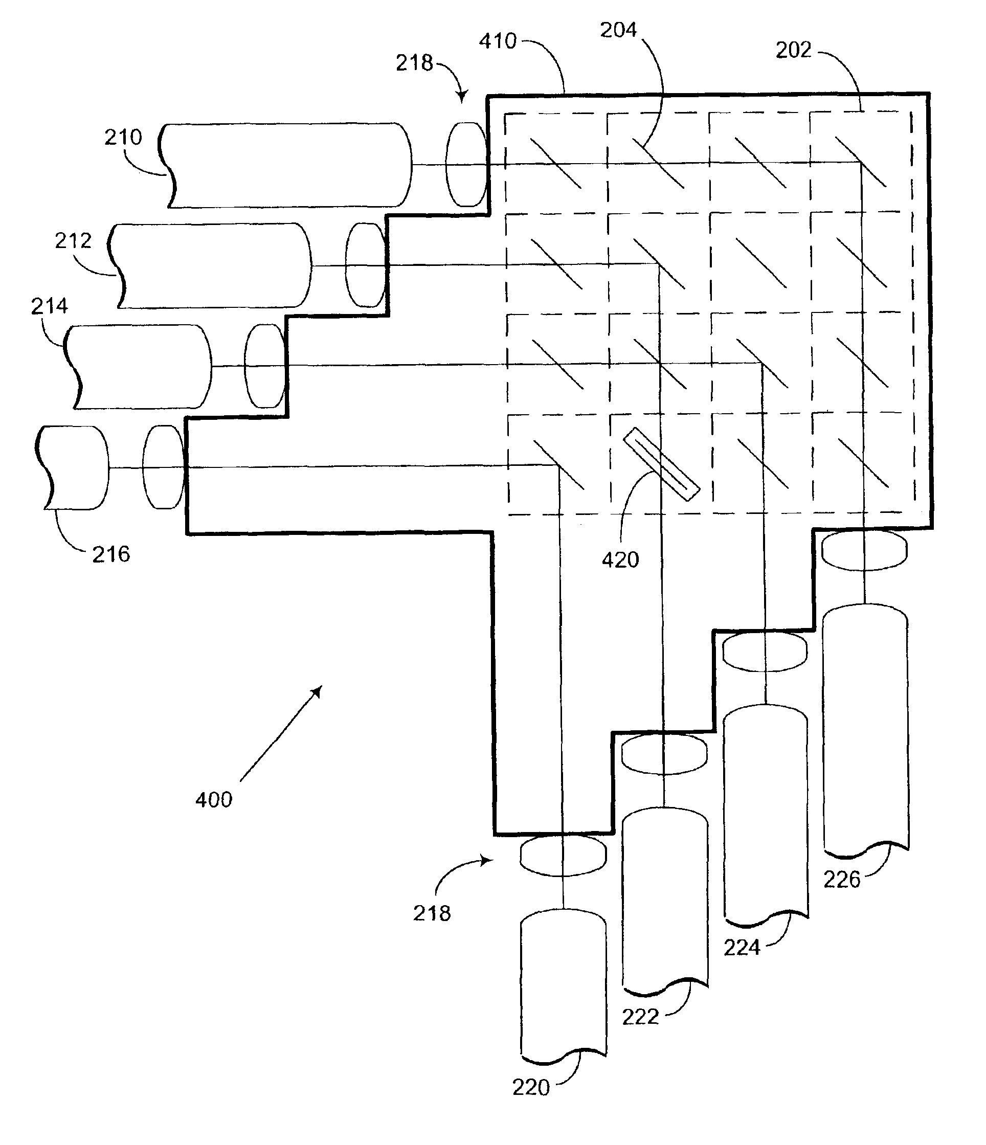
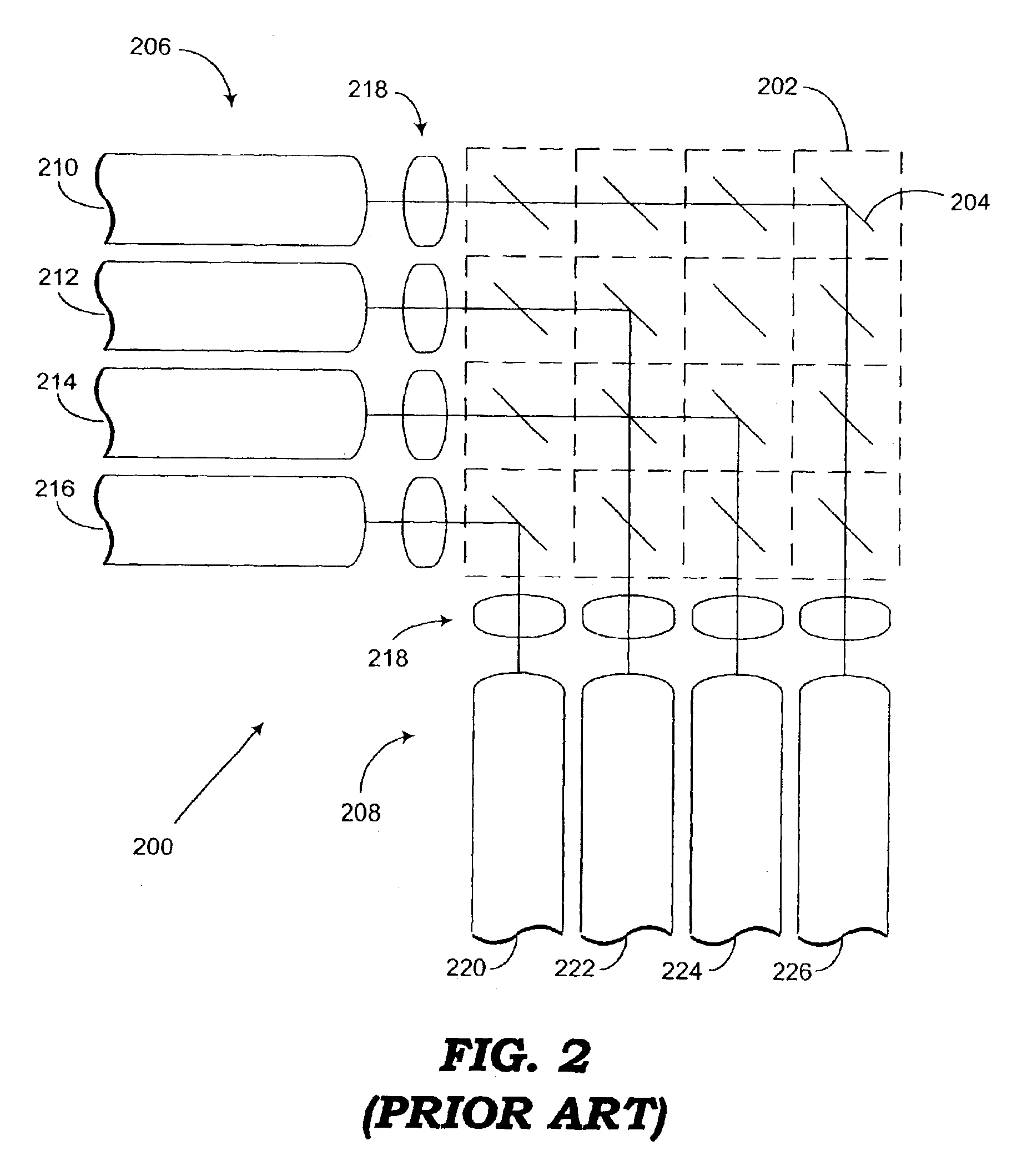
[0024]FIG. 3 is an example of one embodiment of an improved cross-connect optical switch 300. Elements of optical switch 300 that correspond to elements of optical switch 200 are described above with reference to FIG. 2. The same elements are indicated by the same reference numerals and will not be described here. In addition to the common elements shown in FIG. 2, the optical switch 300 includes a refractive material 310 that fills the free space of the prior art optical switch 200. Optical signals propagate through the refractive material 310 from the input optical waveguides 210, 212, 214, 216, and are reflected by the activated micro-mirrors 204. The reflected optical signals further propagate through the refractive material 310 to the respective output optical waveguide 220, 222, 224, 226.

[0025]As shown in FIG. 3, the lenses 218 are positioned between the ends of the optical waveguides and the micro-mirrors 204. The lenses 218 are preferably positioned near or adjacent to an ou...


PUM


Abstract

An optical switch, optical switching method, and a switched optical communication system include at least one micro-mirror in a path along which an optical signal propagates between first and second optical waveguides. Further provided is a refractive material through which the optical signal propagates. The refractive material has a refractive index greater than the refractive index of air. The refractive index of the refractive index may be less than or equal to a refractive index of the optical waveguides.

Description

TECHNICAL FIELD[0001]The technology disclosed herein generally relates to optical communications. More particularly, the technology disclosed herein relates to optical switches for switching optical signals from one of a group of input paths to one of a group of output paths.BACKGROUND DESCRIPTION OF RELATED ART[0002]FIG. 1 is a conceptual block diagram of a simplified prior art optical communication system 100 for exchanging information via optical signals. Multiple optical sources 110-1, 110-2, . . . , 110-M provide optical signals along a corresponding number of input optical waveguides 120-1, 120-2, . . . , 120-M. For example, the input optical waveguides 120 may consist of optical fibers or other light guiding structures. Shown in FIG. 1, the number of optical sources 110 and input optical waveguides 120 is M, which represents any positive integer. The optical signals from the respective optical sources 110 are transmitted by the input optical waveguides 120 to an optical switc...

Claims


Application Information

Patent Timeline
Patent Type & Authority Patents(United States)
IPC IPC(8): G02B6/35G02B6/32B81B7/04G02B6/28G02B26/08
CPCG02B6/3582G02B6/32G02B6/3512G02B6/3556G02B6/3546
Inventor FOUQUET, JULIE E.HOKE, CHARLES D.
Owner AVAGO TECH INT SALES PTE LTD
Why Eureka
Try Eureka