Differential fluid parameter determination

a differential fluid and parameter determination technology, applied in the direction of instruments, liquid/fluent solid measurement, other blood circulation devices, etc., can solve the problems of inconvenient, expensive, uncomfortable medical procedure, and the inability of the gambro method and apparatus to quantitatively determine or measure the recirculation ratio or recirculation efficiency

Inactive Publication Date: 2005-07-05
GAMBRO RENAL PROD
View PDF41 Cites 26 Cited by
  • Summary
  • Abstract
  • Description
  • Claims
  • Application Information

AI Technical Summary

Benefits of technology

[0020]Further in accordance with this aspect of the invention, fluid conductivity is measured by flowing the fluid through a conductivity cell with a continuous path configuration, inducing an electrical current in the fluid in the conductivity cell, and sensing the first electrical current in the first fluid in the first conductivity cell. Still further in accordance with this aspect of the invention, current inducing and sensing may be performed by positioning an exciting electromagnetic coil in proximity with the conductivity cell to induce the electrical current in the continuous path of the conductivity cell, and positioning a sensing electromagnetic coil in proximity with the conductivity cell to sense the induced current. Yet further in accordance with this aspect of the invention, the effects of background conductivity are compensated for.

Problems solved by technology

For example, hemodialysis (herein “dialysis”) is an inconvenient, expensive, and uncomfortable medical procedure.
In the prior art, quantitative determination of recirculation ratio or recirculation efficiency has typically required laboratory testing, such as blood urea nitrogen tests, which take considerable amounts of time and which require withdrawing blood from the patient, which is recognized as undesirable.
The Gambro method and apparatus does not quantitatively determine or measure a recirculation ratio or recirculation efficiency.

Method used


Image

  • Differential fluid parameter determination
  • Differential fluid parameter determination
  • Differential fluid parameter determination

Examples


Embodiment Construction

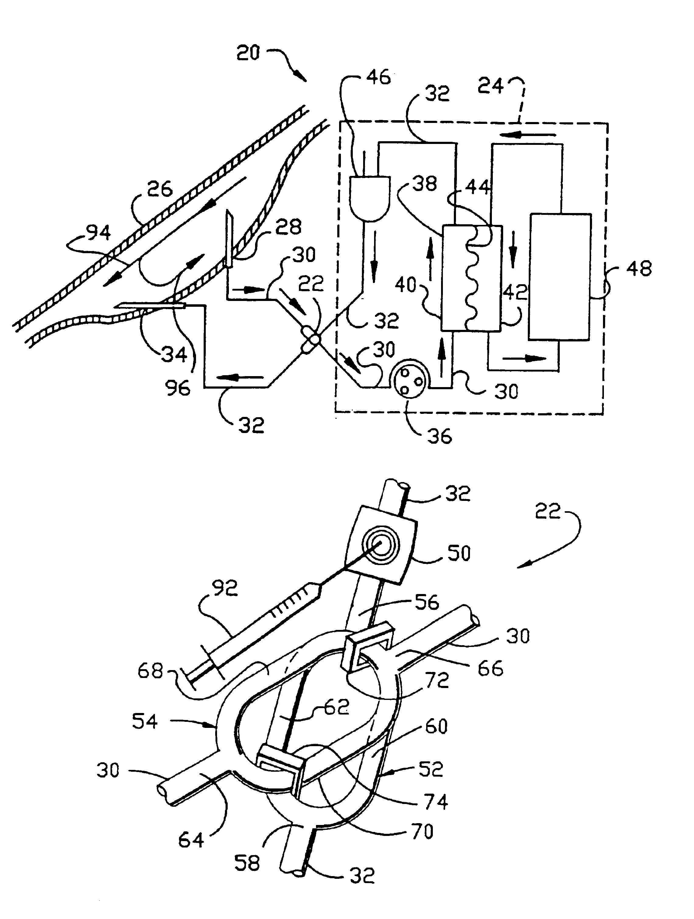
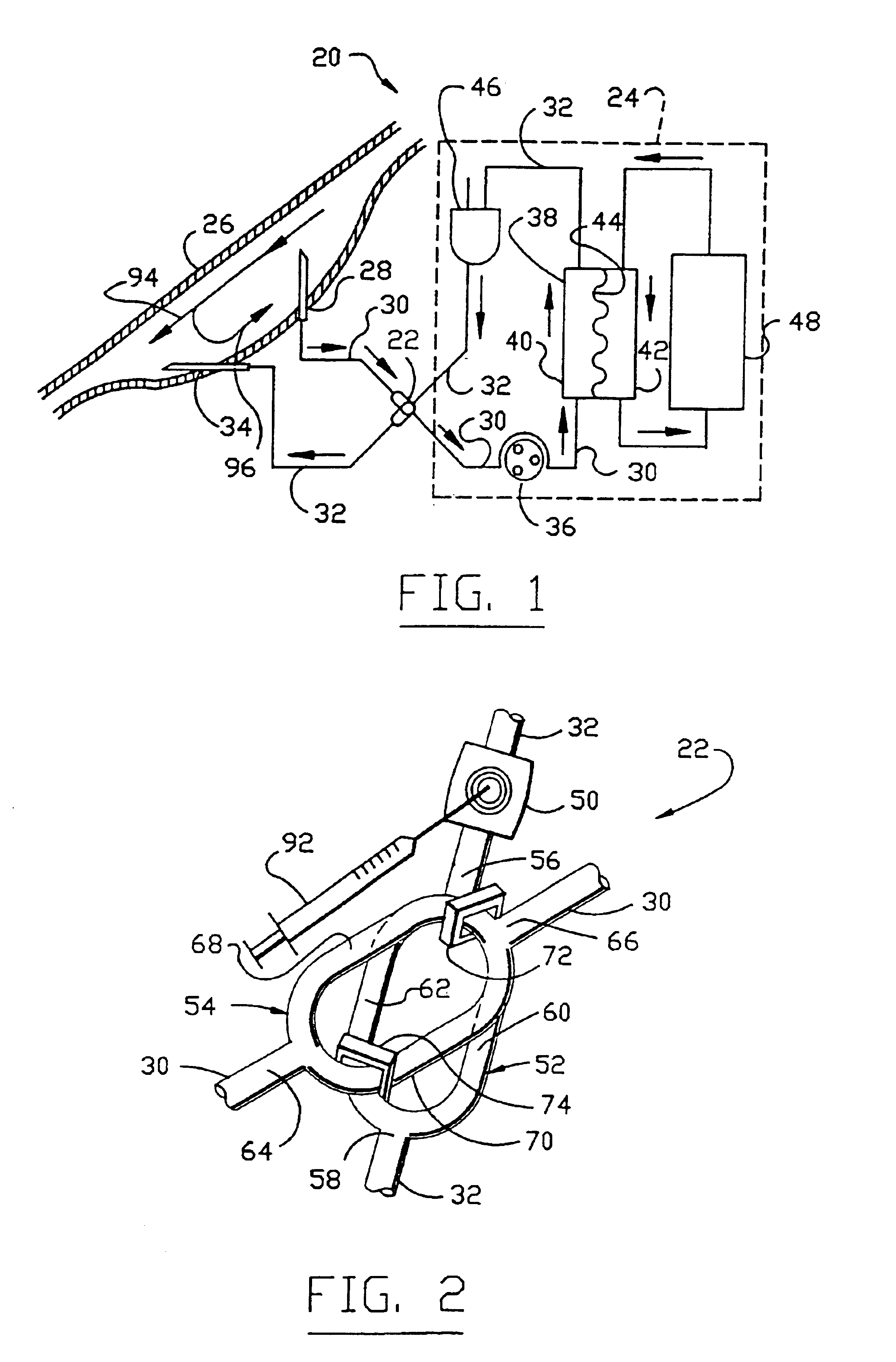
[0034]FIG. 1 illustrates a dialysis system 20 incorporating a differential conductivity recirculation monitor 22 for determining and displaying recirculation efficiency in accordance with the present invention. The dialysis system 20, which is one example of a medical system with which the present invention may be advantageously used, comprises a dialysis apparatus 24 connected to a fistula 26 surgically formed in a dialysis patient (not shown). Untreated blood is drawn from the fistula 26 through a dialyzer inlet needle 28 and a dialyzer inlet line 30. Treated blood is returned to the fistula through a dialyzer outlet line 32 and a dialyzer outlet needle 34. The recirculation monitor 22 is located in the dialyzer inlet and outlet lines 30 and 32 at a point intermediate between the fistula 26 and the dialysis apparatus 24.

[0035]The dialysis apparatus 24 comprises a blood pump 36 typically a peristaltic pump, a dialyzer 38 having a blood compartment 40 and a dialysate compartment 42 ...


PUM

PropertyMeasurementUnit
angleaaaaaaaaaa
physical propertyaaaaaaaaaa
conductivityaaaaaaaaaa

Abstract

Methods and apparatuses for determining a fluid parameter in a vessel by altering a property of the fluid, sensing the difference in the property after the fluid is altered, particularly as related to the property in an unaltered portion of the fluid.

Description

RELATED APPLICATIONS[0001]This patent application is a continuation of U.S. patent application Ser. No. 10 / 238,164 filed Sept. 10, 2002 now U.S. Pat. No. 6,614,212; which is a continuation of U.S. patent application Ser. No. 09 / 563,107 filed May 2, 2000, now U.S. Pat. No. 6,452,371; which is a continuation of U.S. patent application Ser. No. 09 / 220,139 filed Dec. 23, 1998, now U.S. Pat. No. 6,075,367; which is a continuation of U.S. patent application Ser. No. 08 / 876,445 filed Jun. 16, 1997, now U.S. Pat. No. 5,900,726; which was a continuation of U.S. patent application Ser. No. 08 / 486,982 filed Jun. 7, 1995, now U.S. Pat. No. 5,644,240; which was a continuation-in-part of U.S. patent application Ser. No. 08 / 332,647 filed Nov. 1, 1994, now U.S. Pat. No. 5,510,716; which was a continuation of U.S. patent application Ser. No. 07 / 954,584 filed Sept. 30, 1992, now abandoned.FIELD OF THE INVENTION[0002]This invention relates to measurement of multiple hemodynamic variables. More particu...

Claims


Application Information

Patent Timeline
Patent Type & Authority Patents(United States)
IPC IPC(8): A61M1/36A61M1/16G01N27/02G01F1/704G01F1/708G01N33/487G01F1/7088
CPCA61M1/16A61M1/3653A61M1/3669G01F1/7046G01F1/708G01F1/7088A61M1/361A61M1/3612A61M1/3658A61M1/3655A61M1/3659A61M1/3661
Inventor BRUGGER, JAMES M.BUFFALOE, IV, GEORGE W.OGAWA, FRANCIS T.
Owner GAMBRO RENAL PROD
Why Eureka
Try Eureka