

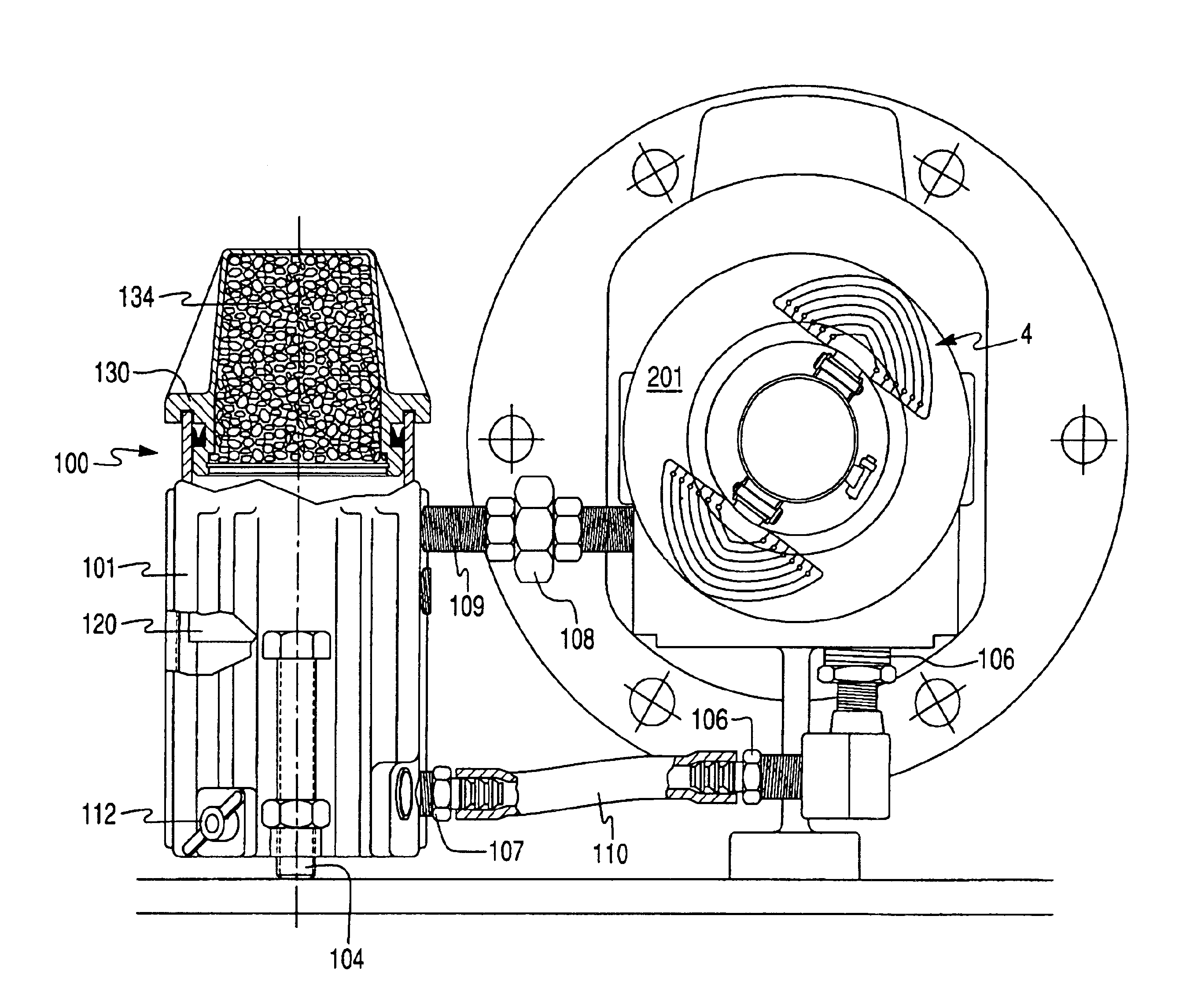
Pump lubrication system including an external reservoir
a lubrication system and pump technology, applied in the direction of piston pumps, positive displacement liquid engines, manual lubrication, etc., can solve the problems of increased maintenance requirements, undesirable heat generation in bearings, and serious harm to the environment, so as to prolong the operating life of bearings and reduce the temperature of oil
- Summary
- Abstract
- Description
- Claims
- Application Information
AI Technical Summary
Benefits of technology
Problems solved by technology
Method used
Image

Examples
Embodiment Construction
[0041]Referring now more particularly to the accompanying drawings in which like reference numerals indicate like parts throughout the several views.
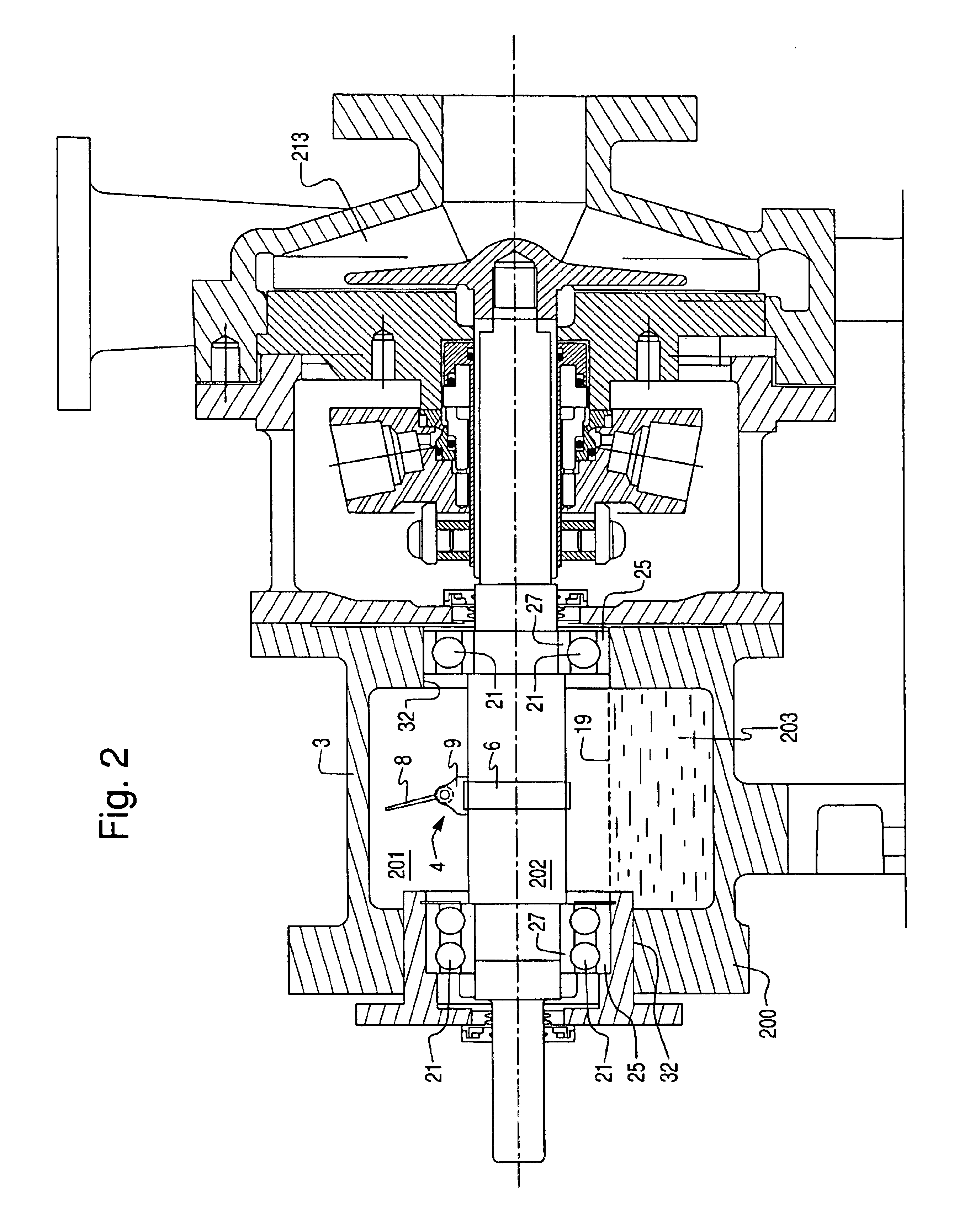
[0042]Below described is a circulating lubrication system according to certain embodiments of this invention used in conjunction with a centrifugal pump including a centrally located rotating shaft. However, it will be understood by those skilled in the art that the lubrication system and corresponding external reservoir according to certain embodiments of this invention may be used in conjunction with other rotating equipment that utilize a lubricant sump for the purpose of lubricating shaft supporting bearings.
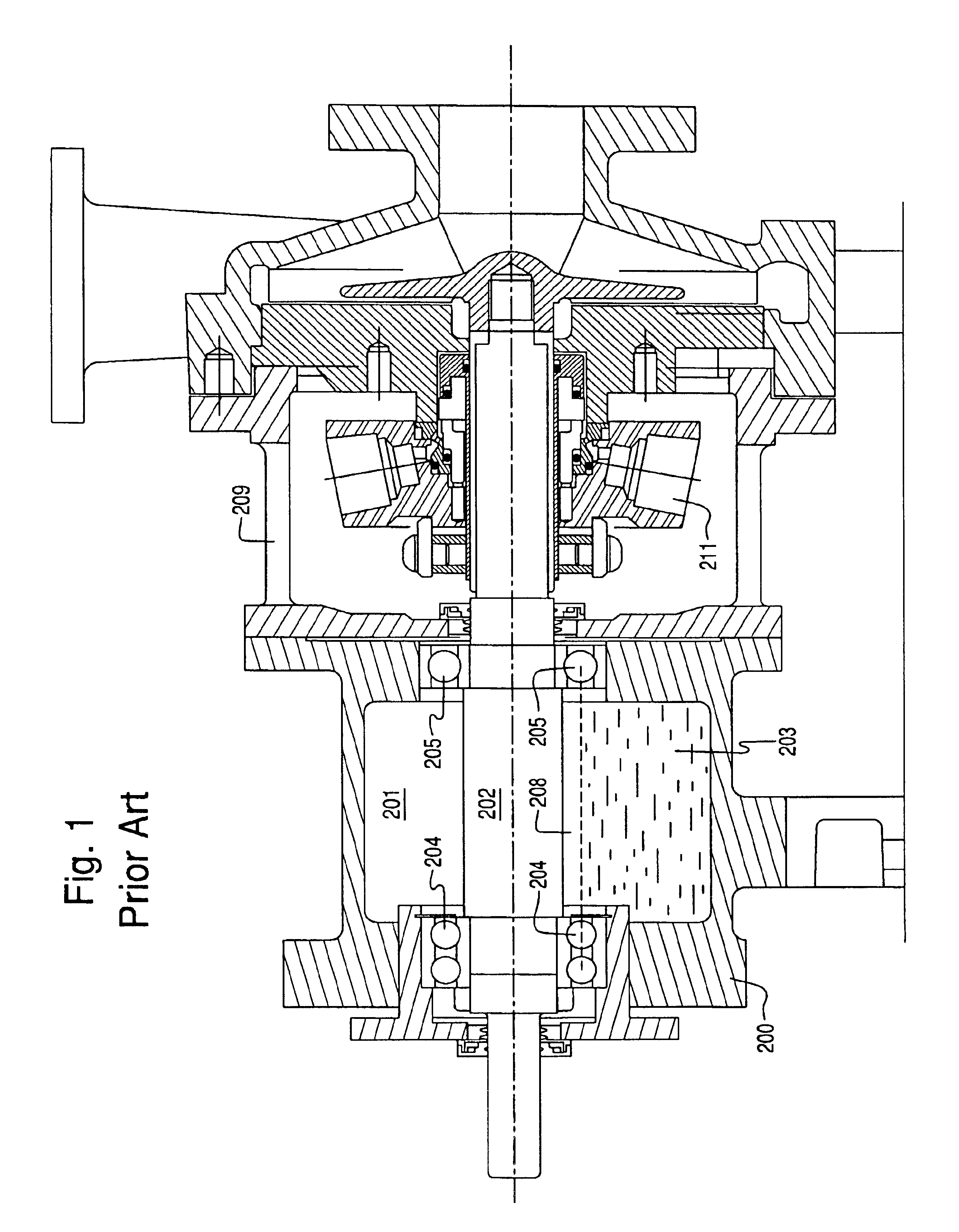
[0043]FIG. 1 illustrates a conventional centrifugal pump including bearings designed for oil lubrication. Bearing lubrication may be accomplished by internal oil misting, internal ring oil lubrication, external sources of oil, and / or flood oil.
[0044]Referring to FIG. 1, the pump includes bearing frame 200, lubrication oil 203, r...
PUM
 Abstract
Description
Claims
Application Information