
Constant velocity universal joint for propeller shaft

a constant velocity, universal joint technology, applied in the direction of yielding couplings, clutches, rotary machine parts, etc., can solve the problems of increasing the weight of the propeller shaft, increasing the number of parts required, and increasing the number of connections, so as to reduce the possibility of the ball interfering with the groove bottom. , the effect of reducing the possibility of interferen

Inactive Publication Date: 2005-07-05
NTN CORP
View PDF16 Cites 22 Cited by
  • Summary
  • Abstract
  • Description
  • Claims
  • Application Information

AI Technical Summary

Benefits of technology

[0023]It is therefore an object of the present invention to provide a constant velocity universal joint for use with a propeller shaft that facilitates reduction in its weight, size, number of parts, man-hours for assembly, and the cost of the vehicle, and provides an improved efficiency of assembling stub shafts and suitability for high speed rotations.

Problems solved by technology

On the other hand, an increase in weight of the propeller shaft would also interfere with high speed rotation of the propeller shaft.
This results in an increase in number of parts required.
An increase in number of parts would result in an increase in number of connections between the parts, thereby causing a degradation of rotational balance in the propeller shaft that rotates at high speeds.
This causes an increase in man-hours required for assembly in addition to an increase in number of parts, thereby resulting in an increase in costs of the vehicle.
However, above the limit rpm-angle value (N·θ), the austenite retained in the components of the ball is varied due to the influence of temperature, thereby resulting in an increase in size.
This is accompanied by an increase in pre-load, which in turn causes the temperature of the constant velocity universal joint to be further increased or results in a significant peak temperature.
However, an increase in tempering temperature has caused another problem to occur which the ball 15 inevitably have a lower hardness, thereby impairing the durability of the constant velocity universal joint.
There is another problem with the conventional Lobro-type constant velocity universal joint.
This would lead to a degradation in presence of lubricant, thereby causing a further increase in temperature.

Method used


Image

  • Constant velocity universal joint for propeller shaft
  • Constant velocity universal joint for propeller shaft
  • Constant velocity universal joint for propeller shaft

Examples


Embodiment Construction

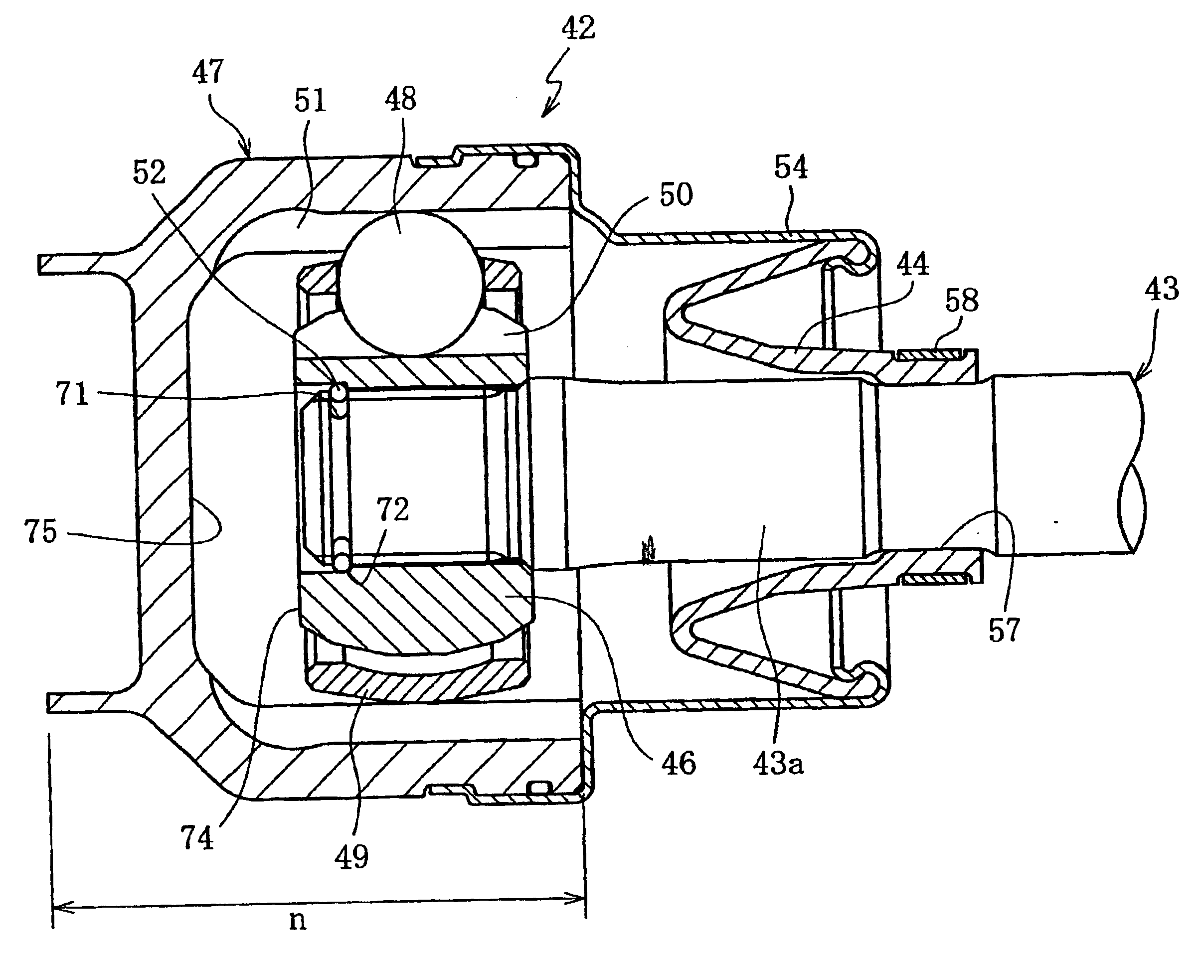
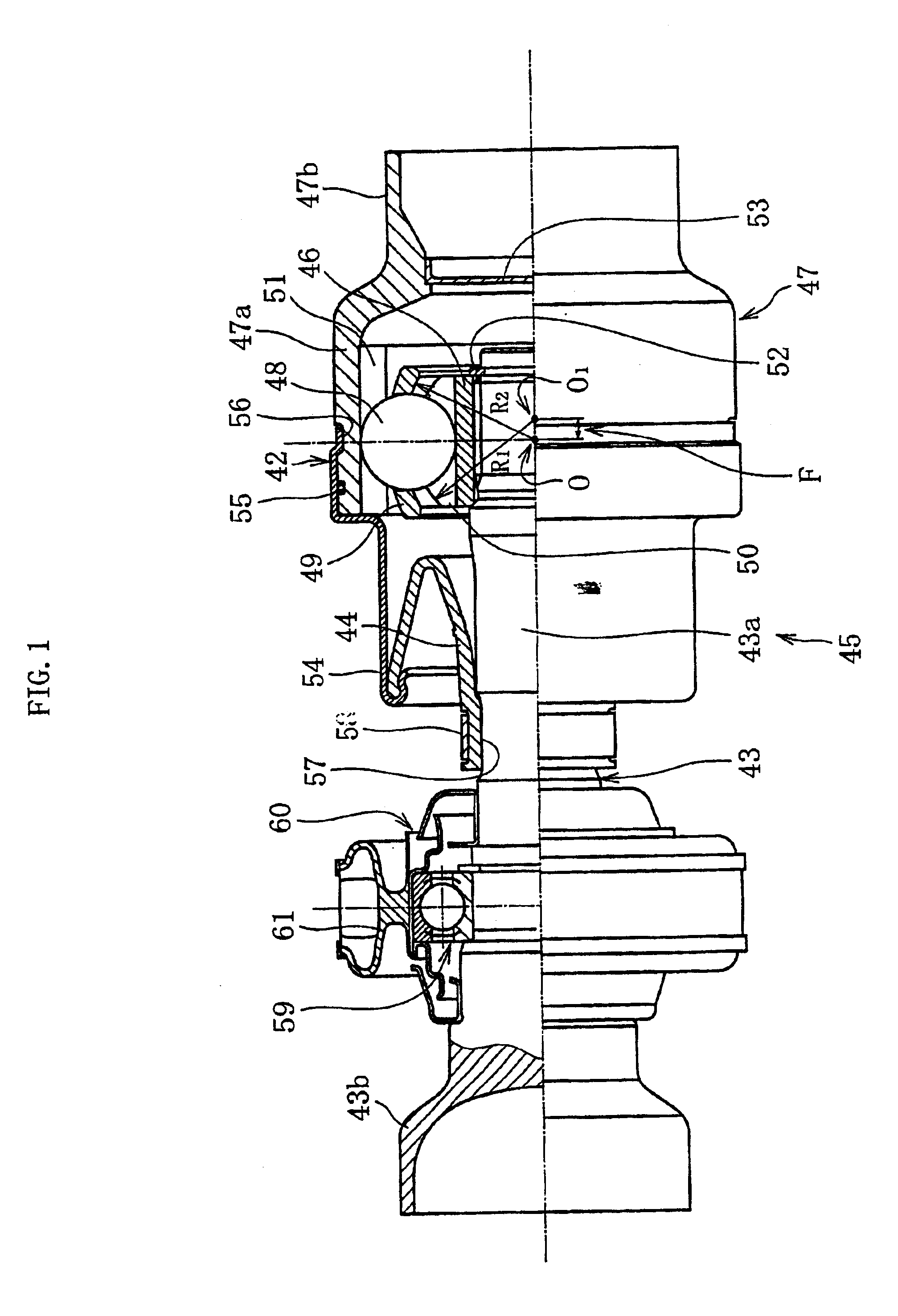
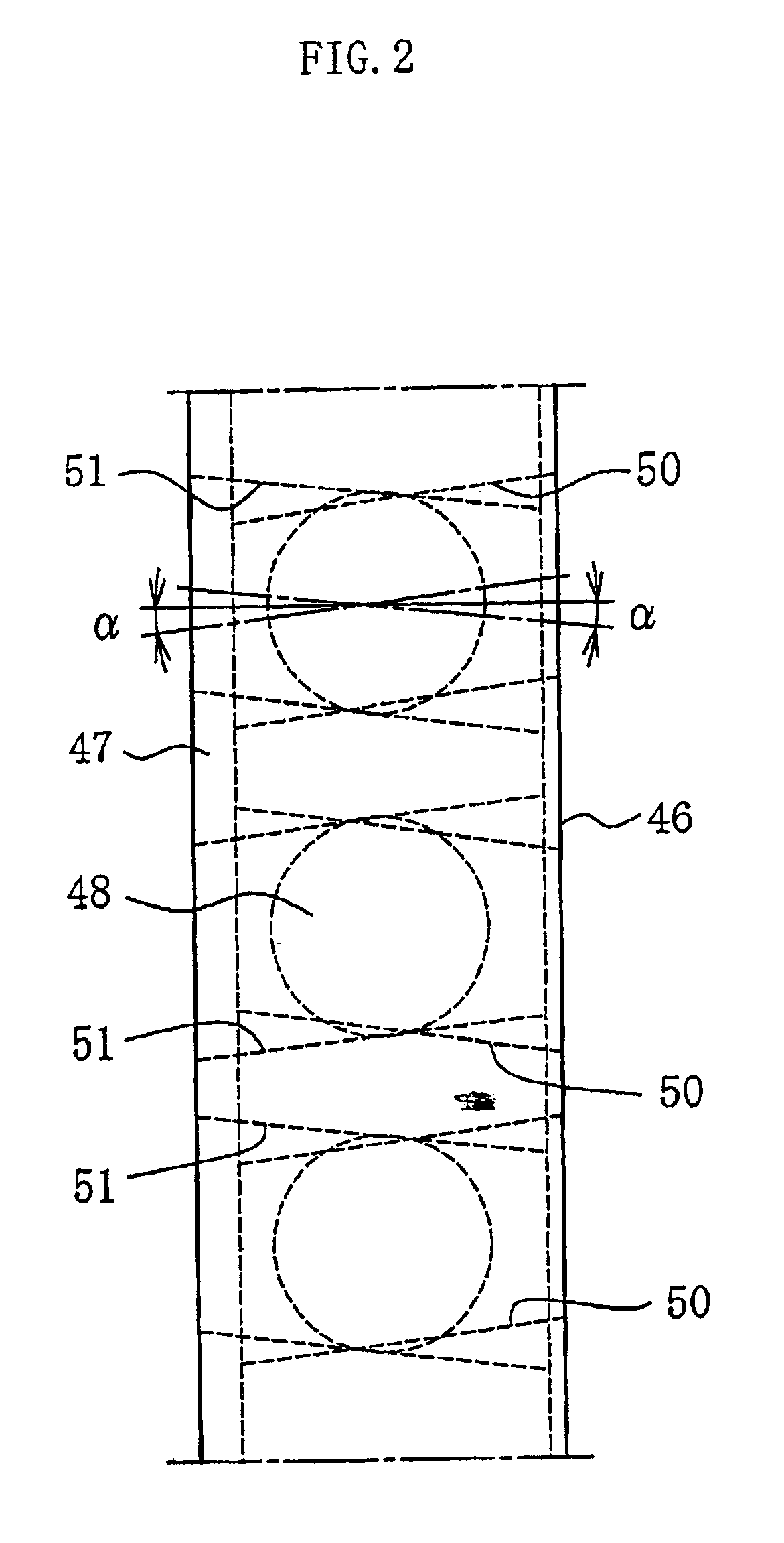
[0075]Now, the present invention will be explained below in more detail with reference to the accompanying drawings in accordance with embodiments. As a sliding constant velocity universal joint that forms a propeller shaft, this embodiment to be described below employs a floating Lobro-type (or cross groove type) constant velocity universal joint, and in particular, a high-speed Lobro-type constant velocity universal joint (LJ) which has a smaller crossing angle of track grooves than a typical Lobro-type constant velocity universal joint and is suitable for high speed rotations. From viewpoint of reducing the weight of an entire vehicle, it is preferable to employ, as a constant velocity universal joint for use with a propeller shaft, a light-weight Lobro-type constant velocity universal joint (LJ) which has a good rotational balance and vibration property with respect to the weight of the universal joint. However, it is still possible to employ a typical Lobro-type constant veloci...


PUM


Abstract

A constant velocity universal joint for use with a propeller shaft which reduces its weight and size as well as facilitates assembling a stub shaft, thereby reducing the number of parts used and improving rotational balance. The universal joint, comprising: an outer ring with a cup-shaped enlarged diameter portion having track grooves formed on an inner peripheral surface and with a hollow reduced diameter portion integrated with the enlarged diameter portion; an inner ring having track grooves formed on an outer peripheral surface; balls, interposed between the track grooves of the inner and outer rings, for transmitting torque; a cage, accommodated in an annular space between the inner and outer rings, for holding the balls. The universal joint makes possible to form a unit provided with a stub shaft, having a shaft portion inserted from an open end portion of the enlarged diameter portion of the outer ring to mate with the inner ring to enable torque transmission and having an enlarged diameter portion on an end portion extending from the shaft portion, and provided with a boot, attached to the open end portion of the enlarged diameter portion of the outer ring and the shaft portion of the stub shaft, for sealing the joint.

Description

BACKGROUND OF THE INVENTION[0001]1. Field of the Invention[0002]The present invention relates to a constant velocity universal joint for use with a propeller shaft that is incorporated into four-wheel drive (4WD) vehicles or front-engine rear-drive (FR) vehicles to transmit a rotational drive force.[0003]2. Description of the Related Art[0004]For example, since an FR vehicle is equipped with an engine, a clutch, and a transmission at the front, and with a differential gear and a drive axle at the rear, respectively, it is common to use a propeller shaft for power transmission therebetween. For an FR-based 4WD vehicle, it is also necessary to equip the vehicle with a rear propeller shaft 6 and a front propeller shaft 3, as shown in FIG. 12. These propeller shafts are equipped with a constant velocity universal joint to accommodate variations in length and angle caused by changes in relative position between the transmission and the differential gears. The propeller shafts are of a do...

Claims


Application Information

Patent Timeline
Patent Type & Authority Patents(United States)
IPC IPC(8): F16D3/16F16D3/223
CPCF16D3/223F16D3/2265F16D2003/22309F16D2003/22313F16D2300/12Y10S464/906Y10S464/902
Inventor IIHARA, MICHIOSAGISAKA, YOSHIHIROKOBAYASHI, MASAZUMISAKAGUCHI, AKIOMANO, RYUMAMAEDA, KIKUO
Owner NTN CORP
Features
  • Generate Ideas
  • Intellectual Property
  • Life Sciences
  • Materials
  • Tech Scout
  • Unparalleled Data Quality
  • Higher Quality Content
  • 60% Fewer Hallucinations
Learn More