Driver circuit

a technology of driving circuit and drive current, which is applied in the direction of electric control, measurement using digital techniques, instruments, etc., can solve the problems of reducing output current, reducing output current, and increasing current beyond normal load current, so as to avoid fault-related discrepancies in much smaller load currents

Inactive Publication Date: 2005-07-05
CONTINENTAL AUTOMOTIVE GMBH
View PDF12 Cites 4 Cited by
  • Summary
  • Abstract
  • Description
  • Claims
  • Application Information

AI Technical Summary

Benefits of technology

[0030]In one variant of the invention, the two current mirror circuits are, by contrast, actuated separately by a respective control input. This affords the advantage that the driver circuit can be configured either as a high-side switch or as a low-side switch. Another advantage of separate actuation of the two current mirror circuits is that the driver circuit can be put into a high-impedance state (tri-state) by turning off both output transistors.

Problems solved by technology

Thus, ground shorting results in a rise in current beyond the normal load current, while battery shorting and line interruption result in a reduction in the output current.
However, a problem in this regard is that the output current from the line driver during the turn-on phase is initially determined by the relatively large charging current for the EMC capacitor, which means that it is not possible to detect fault-related discrepancies in the much smaller load current.
In the known line drivers, the diagnostic function is therefore not available until the EMC capacitor has been largely charged and the charging current has decayed accordingly, so that fault-related discrepancies in the load current can be detected.
A drawback of the known line drivers described above is thus that dynamic identification of a line interruption is not possible during the turn-on phase.
With a fault-free control line, only a portion of this output current charges the EMC capacitor, while the other portion flows via the load and thereby delays the build-up of voltage on the EMC capacitor.
However, a drawback of this is that a line interruption can no longer be identified in this manner during normal operation after the turn-on phase, since a constant current cannot be impressed during normal operation.

Method used


Image

  • Driver circuit
  • Driver circuit
  • Driver circuit

Examples


Embodiment Construction

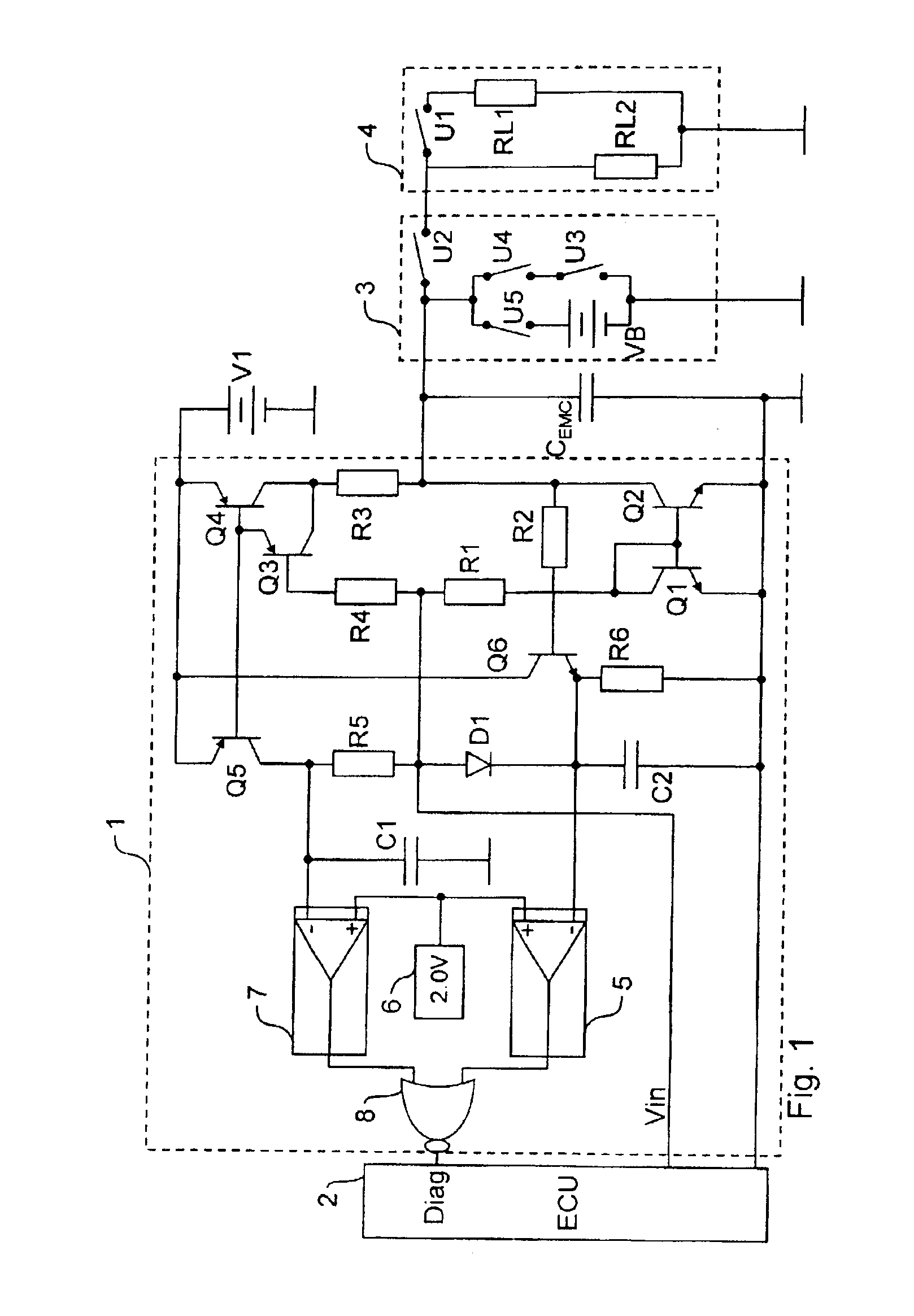
[0035]The text below first describes the structural design of the circuit shown in FIG. 1, which will then be followed by an explanation of the way in which it works.

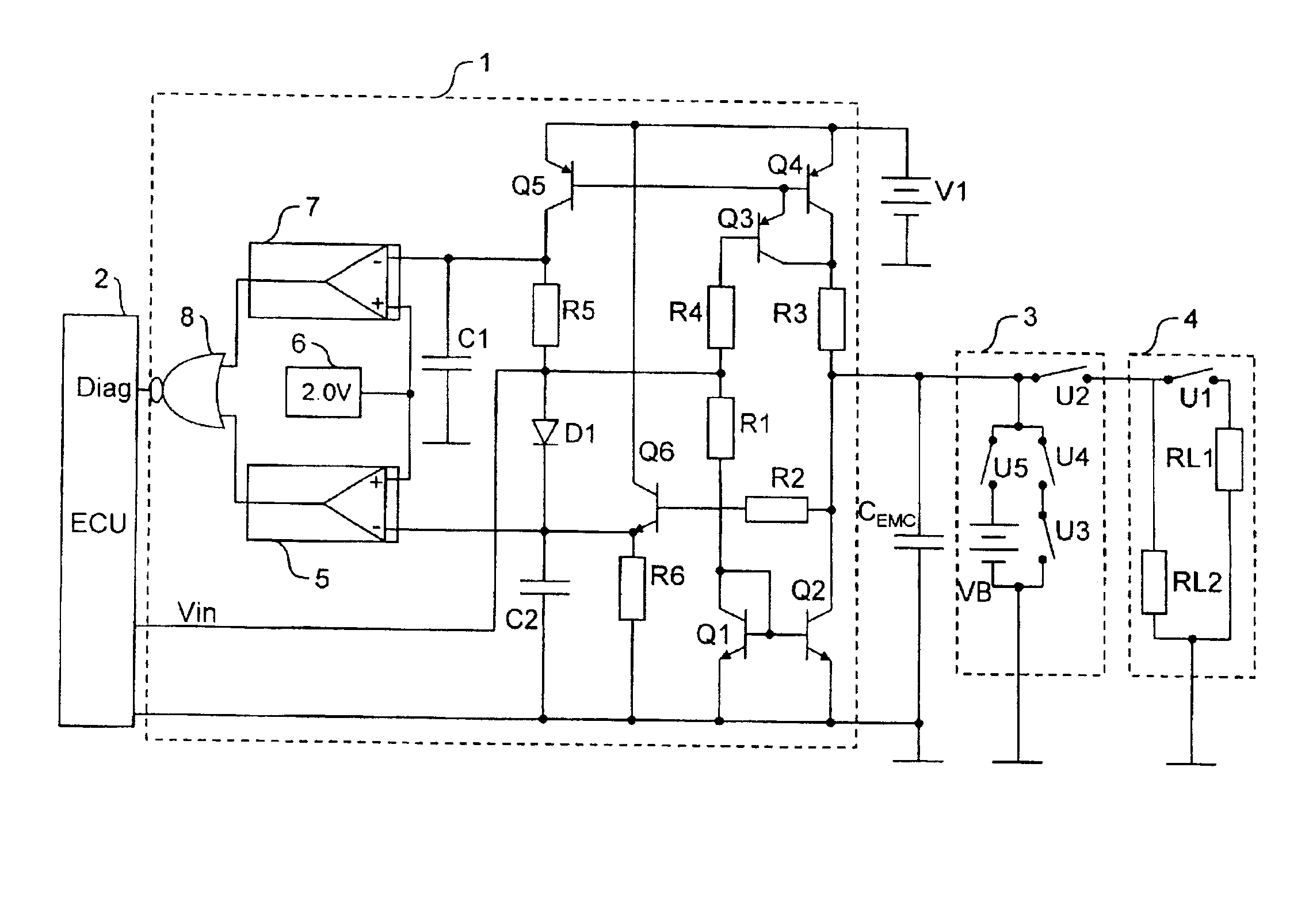
[0036]The circuit diagram shown in FIG. 1 shows an inventive driver circuit 1 which is actuated by an electronic engine controller 2 (ECU—Electronic Control Unit) using a control input Vin, with the driver circuit 1 also returning a diagnostic signal DIAG to the engine controller 2, as will subsequently be explained in detail.

[0037]The output side of the driver circuit 1 is connected by means of a schematically shown control line 3 to an ignition output stage 4, which is likewise shown only schematically.

[0038]In this context, the ignition output stage 4 is shown as an equivalent circuit diagram comprising a switch U1 and two load resistors RL1=2 kΩ and RL2=200 kΩ. The switch U1 in this case allows the load resistance of the ignition output stage 4 to be varied in line with the respective operating state of the ignition...


PUM


Abstract

Driver circuit (1) for actuating an electrical device via a control line (3) and for diagnosing the state of the control line (3) and/or of the actuated device, having a test circuit (Q1-Q6, R1-R6), connected to the control line (3), for measuring the electrical output current flowing via the control line (3), and an evaluation unit (5-8), connected to the test circuit, for generating a diagnostic signal (DIAG) on the basis of the measured output current, the test circuit having at least one current mirror circuit (Q1, Q2; Q4-Q5).

Description

PRIORITY[0001]This application claims foreign priority of the German application DE 10202289.5 filed on Jan. 22, 2002.BACKGROUND OF THE INVENTION[0002]The invention relates to a driver circuit for actuating an electrical device via a control line and for diagnosing the state of the control line and / or of the actuated device[0003]In modem, electronically controlled internal combustion engines, the ignition output stage is known to be actuated by the electronic engine controller using line drivers, with the line drivers needing to meet various requirements.[0004]By way of example, the line drivers need to produce rapid switching edges having a switching time of just 0.5-2 μs even if a capacitor is grounded at the output of the line driver for the purpose of EMC suppression.[0005]In addition, the line drivers need to be sufficiently resistant to ground and battery shorting and to any interruption in the control line.[0006]Finally, the line drivers need to allow diagnosis of shorting to...

Claims


Application Information

Patent Timeline
Patent Type & Authority Patents(United States)
IPC IPC(8): F02D41/20F02P3/02F02P3/055G01R19/25G01R31/00G01R19/00G01R31/02G01R31/50
CPCF02D41/20F02P3/0554G01R19/0092G01R19/2513G01R31/006F02D2041/2058F02D2041/2093G01R31/005G01R31/007G01R31/024G01R31/50
Inventor BOLZ, STEPHAN
Owner CONTINENTAL AUTOMOTIVE GMBH
Why Eureka
Try Eureka