
Disk unit, yoke built in disk unit and process of manufacturing same

a technology of yoke and disk unit, which is applied in the direction of magnetic recording, data recording, instruments, etc., can solve the problems of undesirable leakage flux, irregular noise, and leakage flux through the yoke, and achieve the effect of effectively suppressing leakage flux, easy manufacturing, and low cos

Inactive Publication Date: 2005-07-05
KK TOSHIBA
View PDF13 Cites 6 Cited by
  • Summary
  • Abstract
  • Description
  • Claims
  • Application Information

AI Technical Summary

Benefits of technology

[0010]The object of the invention is to provide a yoke which can be inexpensively and easily manufactured, effectively suppress leakage flux and exercise sufficient performance, a disk unit provided with this yoke, and a process of manufacturing this yoke.
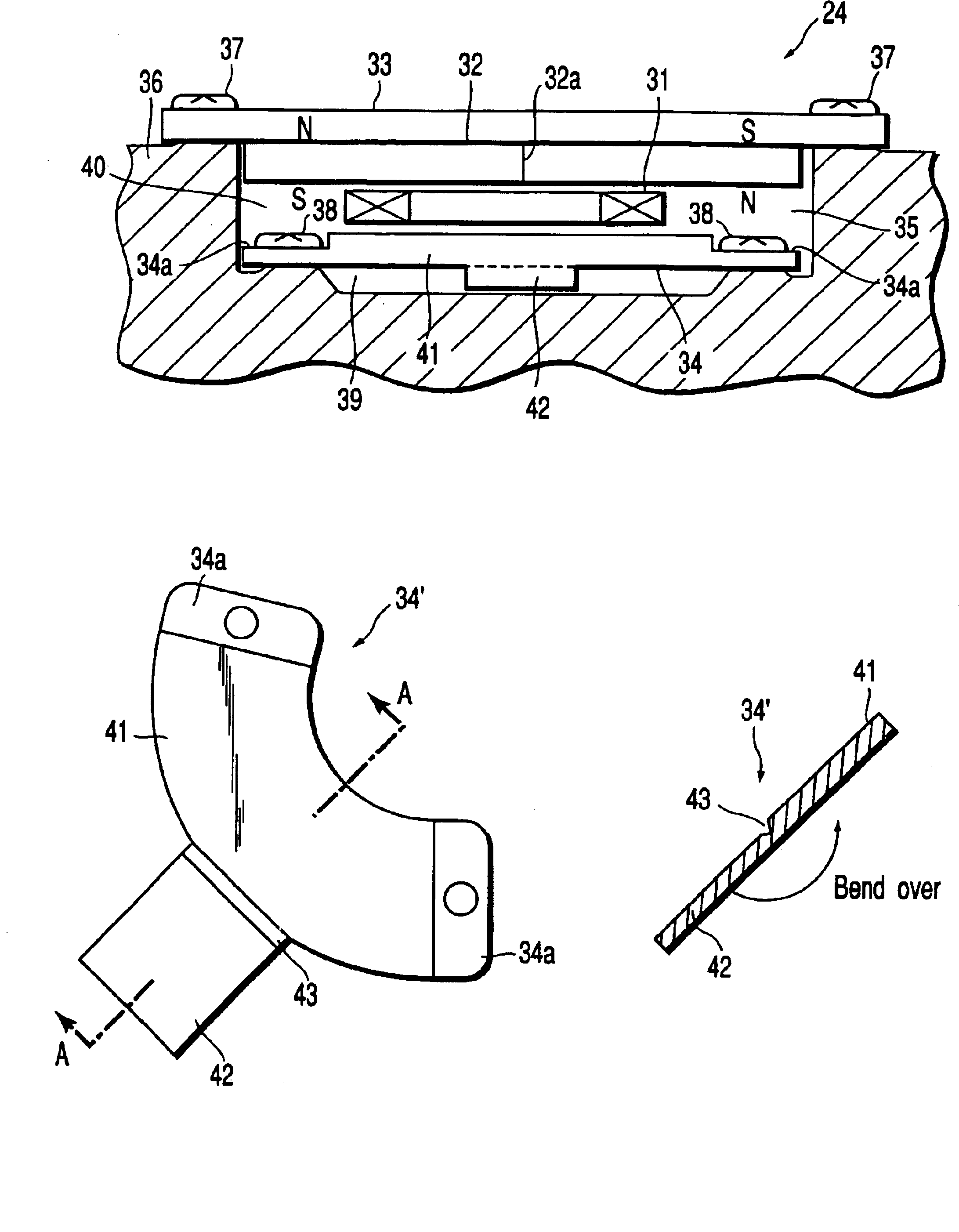
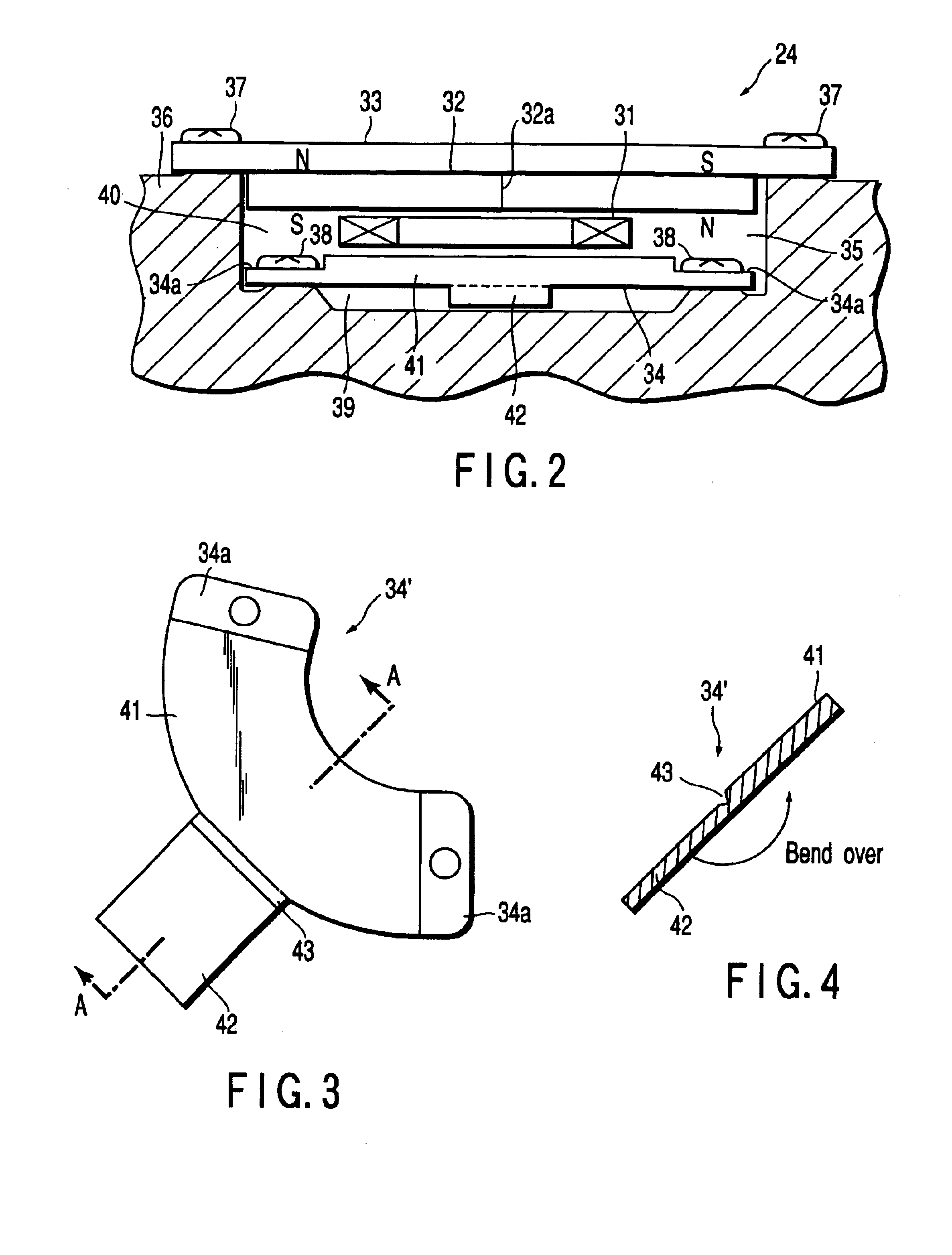
[0012]According to this embodiment, the main body and plate piece portion can be simultaneously formed, for example, by press working and the yoke can be manufactured simply by folding the plate piece portion onto the main body. In addition, the thickness of a desired portion of the yoke can be easily and selectively increased and the generation of leakage flux to the outside can be effectively suppressed in a condition where a magnetic circuit is formed with the magnet sandwiched.
[0015]According to this embodiment, the yoke can be manufactured simply by simultaneously forming the main body and the plate piece portion by press working and folding the plate piece portion onto the main body. Because the yoke thickness is increased by this method, the step of attaching the plate piece portion to the main body becomes unnecessary, with the result that the number of parts and manufacturing steps can be reduced and that the yoke manufacturing cost can be reduced.

Problems solved by technology

However, the above-described conventional voice coil motor had the problem that a leakage flux through the yoke occurs.
That is, when the yoke is made thin for miniaturization and weight reduction of the disk unit, magnetic saturation occurs in the yoke, generating an undesirable leakage flux.
When a leakage flux is generated, undesirable magnetic fields are generated inside and outside the unit, thus posing the problem that irregularities such as noise occur.
Although it is, therefore, conceivable to increase the yoke thickness in the direction of the magnetic flux of magnet, the yoke becomes heavy, and this idea is inconsistent with weight reduction.
Furthermore, attaching a plate piece or the like, as a separate body, to the yoke in order to increase the thickness, poses the problem that the manufacturing cost increases.

Method used


Image

  • Disk unit, yoke built in disk unit and process of manufacturing same
  • Disk unit, yoke built in disk unit and process of manufacturing same
  • Disk unit, yoke built in disk unit and process of manufacturing same

Examples


Embodiment Construction

[0022]An embodiment of the invention will be described in detail below by referring to the drawings.

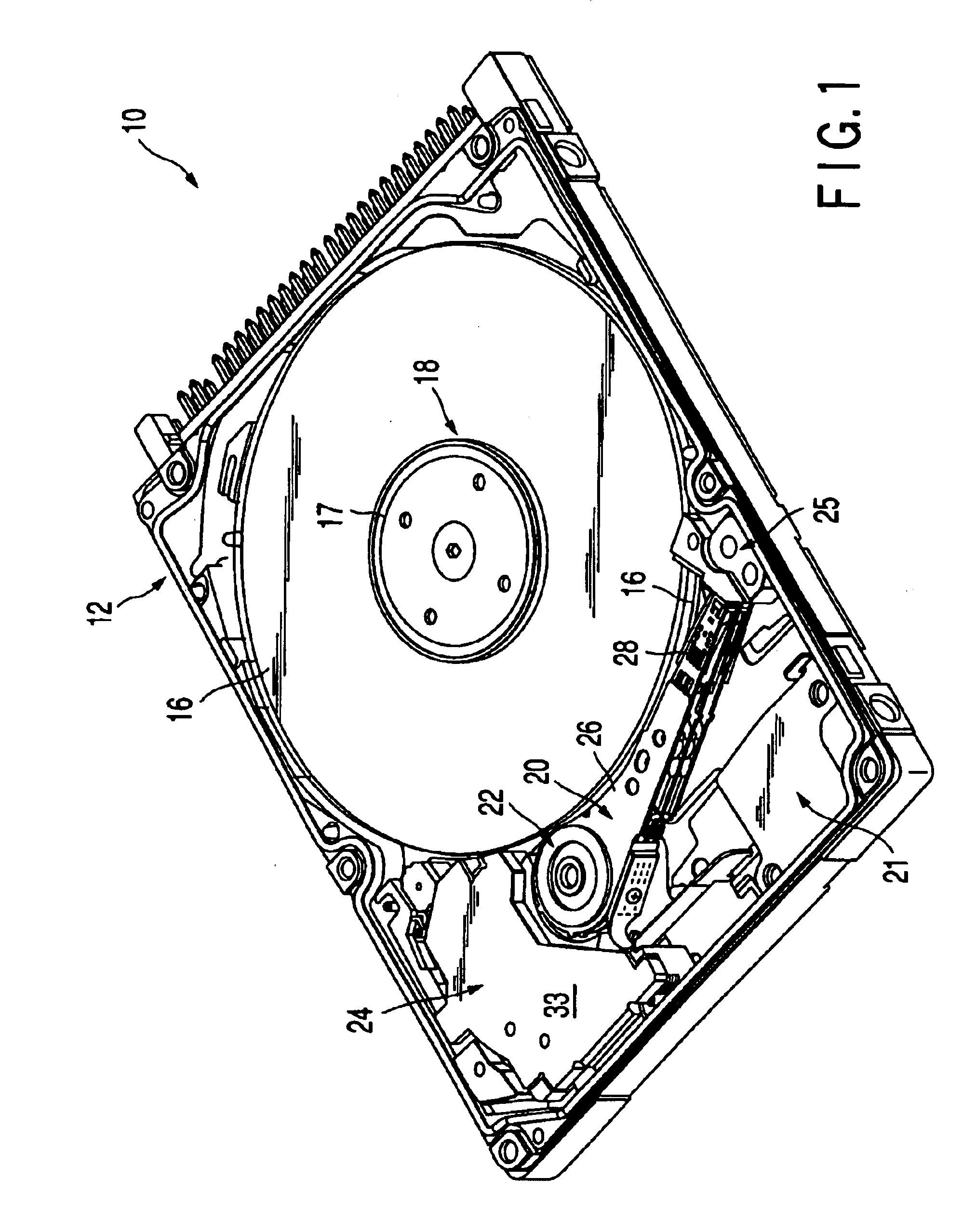
[0023]In FIG. 1 is shown the rough structure, in perspective, of a hard disk drive 10 (hereinafter referred to as an HDD 10) as a disk unit related to an embodiment of the invention.

[0024]The HDD 10 has a case 12 in the shape of a rectangular box having an open top face, and a top cover (not shown) which closes the top-end opening of the case 12 by being screwed to the case 12 by application of multiple twists. That is, FIG. 1 shows a condition in which the top cover is removed in order to illustrate the inner structure of the HDD 10.

[0025]Within the case 12 are housed, for example, two magnetic disks 16 as recording media, a spindle motor 18 which supports and rotationally drives these magnetic disks 16, four suspension arms 20, which are each provided, at their respective leading ends, with a magnetic head (not shown) which performs the reading and writing of information from and to...


PUM

PropertyMeasurementUnit
diameteraaaaaaaaaa
thicknessaaaaaaaaaa
magnetic fluxaaaaaaaaaa

Abstract

A disk unit has a voice coil motor to oscillate a suspension arm mounted at the leading end of a head with respect to a disk. The voice coil motor has a voice coil integrally attached to the tail end of the suspension arm, a magnet to cause a magnetic field to act on the voice coil, and a pair of yokes provided in such a positional relationship that the voice coil and magnet are sandwiched therebetween. At least one yoke has a roughly fan-shaped main body and a plate piece portion provided in a condition extended from one end side of the main body. After the formation of the main body and plate piece portion by press working, the yoke is formed by folding the plate piece portion on the main body.

Description

CROSS-REFERENCE TO RELATED APPLICATIONS[0001]This application is based upon and claims the benefit of priority from the prior Japanese Patent Application No. 2001-290243, filed Sep. 21, 2001, the entire contents of which are incorporated herein by reference.BACKGROUND OF THE INVENTION[0002]1. Field of the Invention[0003]The present invention relates to a disk unit which performs the writing and reading of data to and from a medium in the form of a disk, a yoke built into this disk unit and a process of manufacturing this yoke.[0004]2. Description of the Related Art[0005]A disk unit comprises a spindle motor which supports and rotates a medium in the form of a disk (hereinafter referred to simply as a disk), a head which performs the writing and reading of data to and from the disk, a suspension arm which is provided, at its leading end, with the head and which causes the head to be opposed to a desired track on the disk by oscillating the head, a bearing which oscillatably supports ...

Claims


Application Information

Patent Timeline
Patent Type & Authority Patents(United States)
IPC IPC(8): G11B5/55G11B21/02
CPCG11B5/5521
Inventor YANAGIHARA, SHIGEKI
Owner KK TOSHIBA
Learn More