
Method of operating a remote control system and a remote control system comprising an RF transmission and receiving system

a remote control system and receiving system technology, applied in the field of remote control systems and remote control systems comprising rf transmission and receiving systems, can solve the problems of inability to easily recover ir signals from transmitted rf (radio frequency) signals, inability to obtain low-cost rf transmission, and inability to handle a wide range of ir sub-carrier frequencies. achieve the effect of convenient retrieval, simple and cost-effectiv

Inactive Publication Date: 2005-07-05
KONINKLIJKE PHILIPS ELECTRONICS NV
View PDF3 Cites 10 Cited by
  • Summary
  • Abstract
  • Description
  • Claims
  • Application Information

AI Technical Summary

Benefits of technology

[0006]It is an object of the invention to provide a method and system with which, in a relatively simple and cost effective manner the IR signal is more readily retrievable from the transmitted RF signal.
[0015]An extra problem occurs with IR codes that use even higher sub-carrier frequencies than 100 kHz (499 kHz, 1 MHz, . . . as used by certain manufacturers). For these frequencies it is impossible to make a low-cost RF transmission.
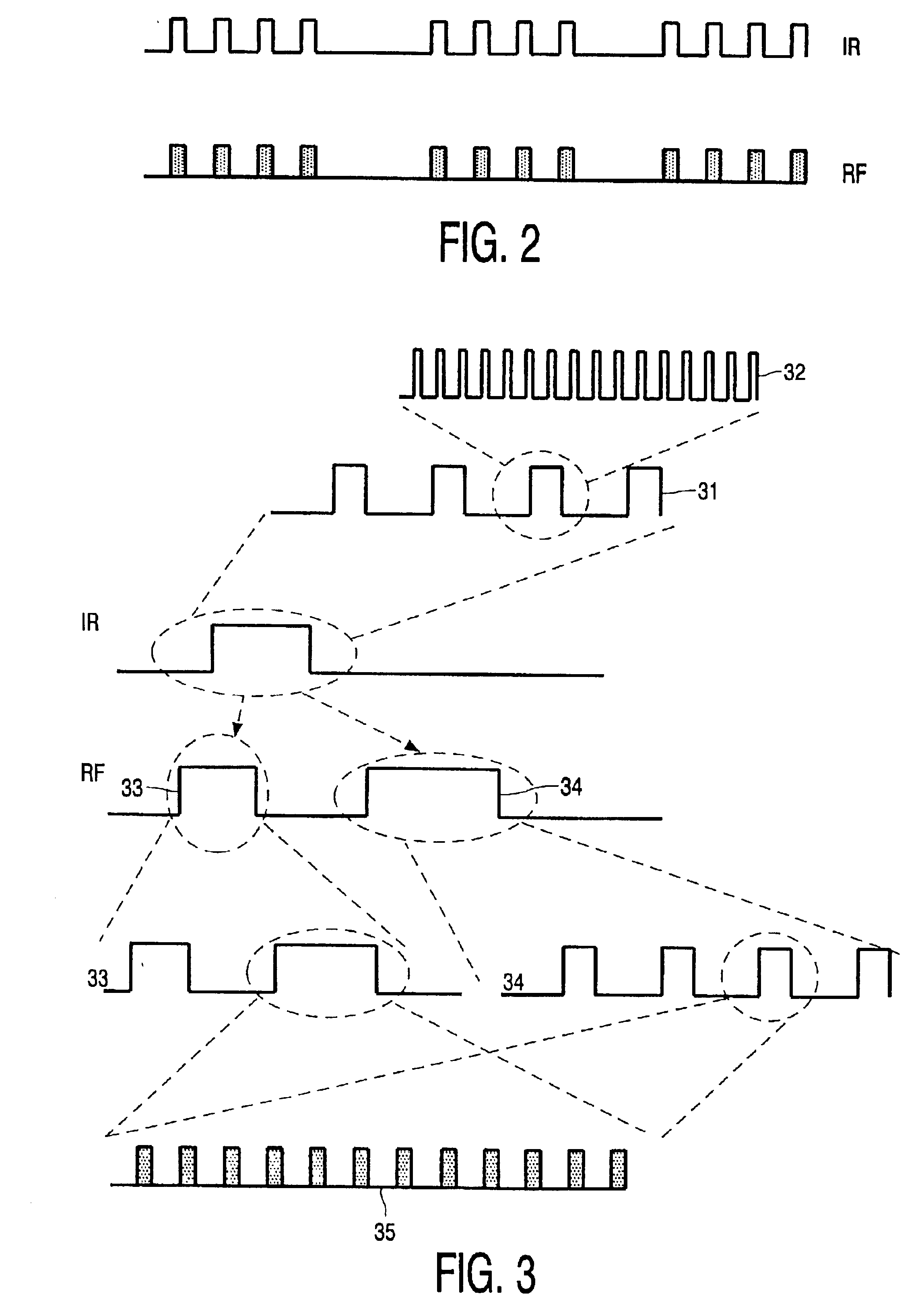
[0016]To overcome these problems in the present invention the IR sub-carrier is removed from the IR message leaving only the envelope of the IR message. The information about the sub-carrier is put in an extra RF message that is e.g. sent as a kind of header message in front of the original message. The RF signal, containing both the header and the original message (envelope), are modulated on a fixed frequency (sub-carrier) that allows an easy modulation of the RF carrier and easy recovery from the transmitted RF signal on the RF receiver side. The two messages, header (carrier information) and data (envelope), are brought together again on the RF receiver side to reconstruct the original IR message.
[0017]The invention further allows the optimization of the RF link and it allows the transmission of IR codes (via the R-F link) with virtually any possible carrier frequency.

Problems solved by technology

The existing systems, however, are not well equipped to handle a wide range of IR sub-carrier frequencies and because the IR signal can have various coding schemes the IR signal is not always easily recovered from the transmitted RF (radio frequency) signal.
Also for high frequencies low-cost RF transmission is impossible or at least hard to obtain.

Method used


Image

  • Method of operating a remote control system and a remote control system comprising an RF transmission and receiving system
  • Method of operating a remote control system and a remote control system comprising an RF transmission and receiving system
  • Method of operating a remote control system and a remote control system comprising an RF transmission and receiving system

Examples


Embodiment Construction

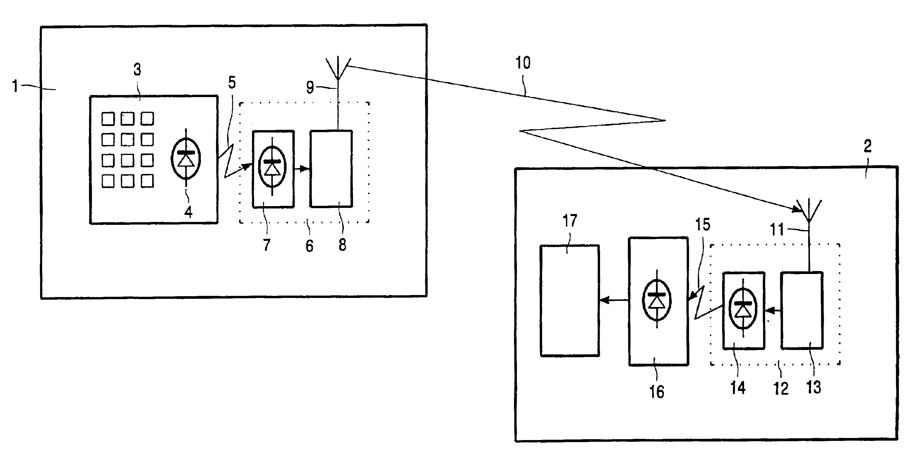
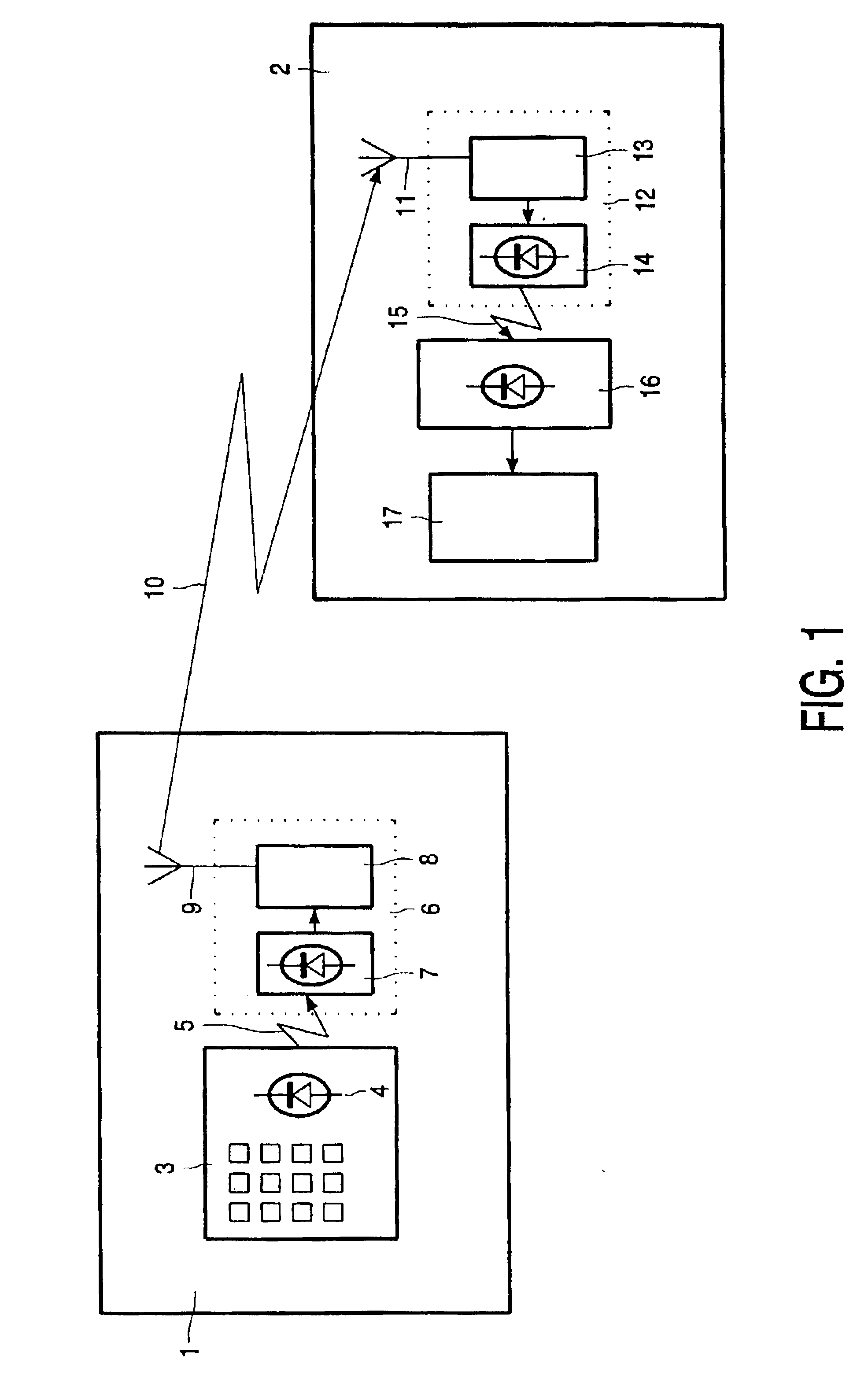
[0031]FIG. 1 schematically illustrates an embodiment of the method and systems of the invention in which the range of an infrared remote control system is extended. In a room 1 and a separate room 2 the following elements are present. An infrared remote control unit 3 comprises an infrared transmitter 4 for transmitting an IR signal 5 on an IR sub-carrier, an RF transmission system 6 comprises an infrared receiver 7 coupled to a radio transmitter 8 for transmitting a radio signal 10 (in this example via antenna 9) in response to a infrared signal 5.

[0032]The radio signal 10 is received via antenna 11 by radio receiver 13, which is coupled to IR transmitter 14 for generating IR signal 15. This is received by IR receiver 16 which is coupled to a device to be controlled such as an VCR.

[0033]FIG. 2 schematically illustrates a feature of the method and system known so far. All existing converters do a direct conversion of the IR signal to an R-F signal and vice versa. This means that the...


PUM


Abstract

In a method of operating a remote control system and in such a system comprising an RF transmission and receiving system and an IR transmission device the sub-carrier information of the IR signal is transmitted in the RF signal in a signal separate from the envelope information of the IR signal which is contained in a envelope signal.

Description

FIELD OF THE INVENTION[0001]The invention relates to a method of operating a remote control system comprising an RF transmission and receiving system which comprises a radio transmitter for transmitting an RF signal and a radio receiver for receiving the RF signal transmitted by the radio transmitter, said receiver being coupled to an infrared transmitter for transmitting an IR signal on an IR sub-carrier in response to the receipt of said RF signal.[0002]The invention also relates to a remote control system comprising an RF transmission and receiving system which comprises a radio transmitter for transmitting an RF signal and a radio receiver for receiving an RF signal transmitted by the radio receiver coupled to an infrared transmitter for transmitting an IR signal on an IR sub-carrier in response to the receipt of said RF signal.[0003]The invention may be used in a variety of systems and devices inter alia, but not restricted to, systems comprising or using remote control, VCR, T...

Claims


Application Information

Patent Timeline
Patent Type & Authority Patents(United States)
IPC IPC(8): G08C17/00G08C17/02H04B10/10H04J1/00G08C19/28G08C23/04H04B7/15H04B10/114H04Q9/00H04Q9/12
CPCG08C17/02H04B10/114G08C2201/40H04Q9/00
Inventor WOUTERS, JOHAN AGNES EMILENICKSON, ROBERT EDMOND VICTOR A.LAMBRECHTS, MARC EMIEL CELINEPHUAH, CHOOKHOON
Owner KONINKLIJKE PHILIPS ELECTRONICS NV
Learn More