USB interface controller chip

a controller chip and usb interface technology, applied in the field of usb interface controller chips, can solve the problems of increasing the cost, increasing the possibility of being damaged by electro-static discharge, and increasing the cos

Inactive Publication Date: 2005-07-05
ELAN MICROELECTRONICS CORPORATION
View PDF4 Cites 6 Cited by
  • Summary
  • Abstract
  • Description
  • Claims
  • Application Information

AI Technical Summary

Benefits of technology

[0006]One object of the present invention is to provide a USB interface controller chip integrated with a pull-up resistor without violating the consistence to USB transmission scheme, in which the pull-up resistor built in the controller chip could have a tolerance range larger than that defined by USB specification.

Problems solved by technology

However, the USB low-speed device controller chip 12 together with an external pull-up resistor Rpu results in a higher cost, and the controller chip 12 needs to be provided with one additional pin for connection of the external pull-up resistor Rpu and thus not only increasing the cost, but also increasing the possibility of being damaged by electro-static discharge (ESD).
In addition to the cost down of the device manufacturer, the pin count on the chip package will be decreased by one and thereby is decreased the possibility of ESD damages if the pull-up resistor Rpu could be integrated within a single chip.
Nevertheless, the polysilicon resistor formed by the normal semiconductor processes in combination with the temperature drift may have a tolerance approximately ranged from 10% to 20%, it is therefore difficult for the pull-up resistor Rpu to be built in a single chip to satisfy the USB specification requirement, unless special and thus expensive process is used.

Method used


Image

  • USB interface controller chip
  • USB interface controller chip
  • USB interface controller chip

Examples


Embodiment Construction

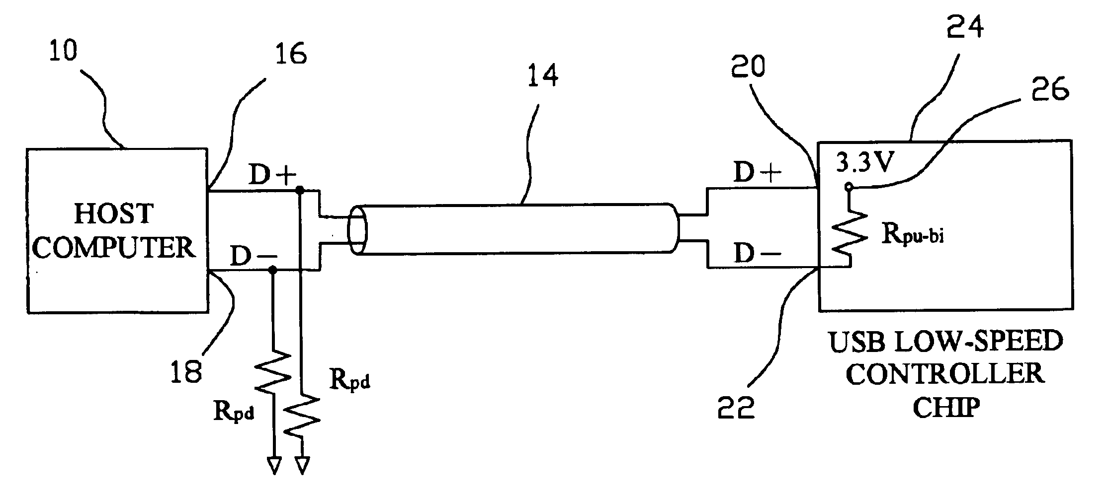
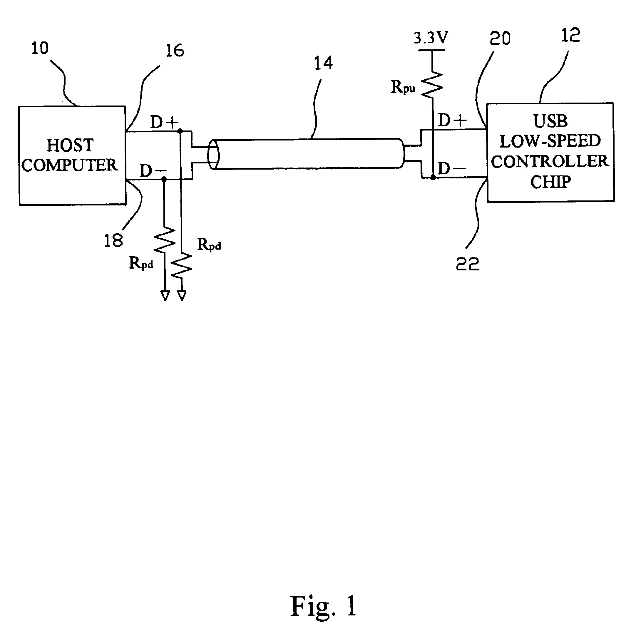
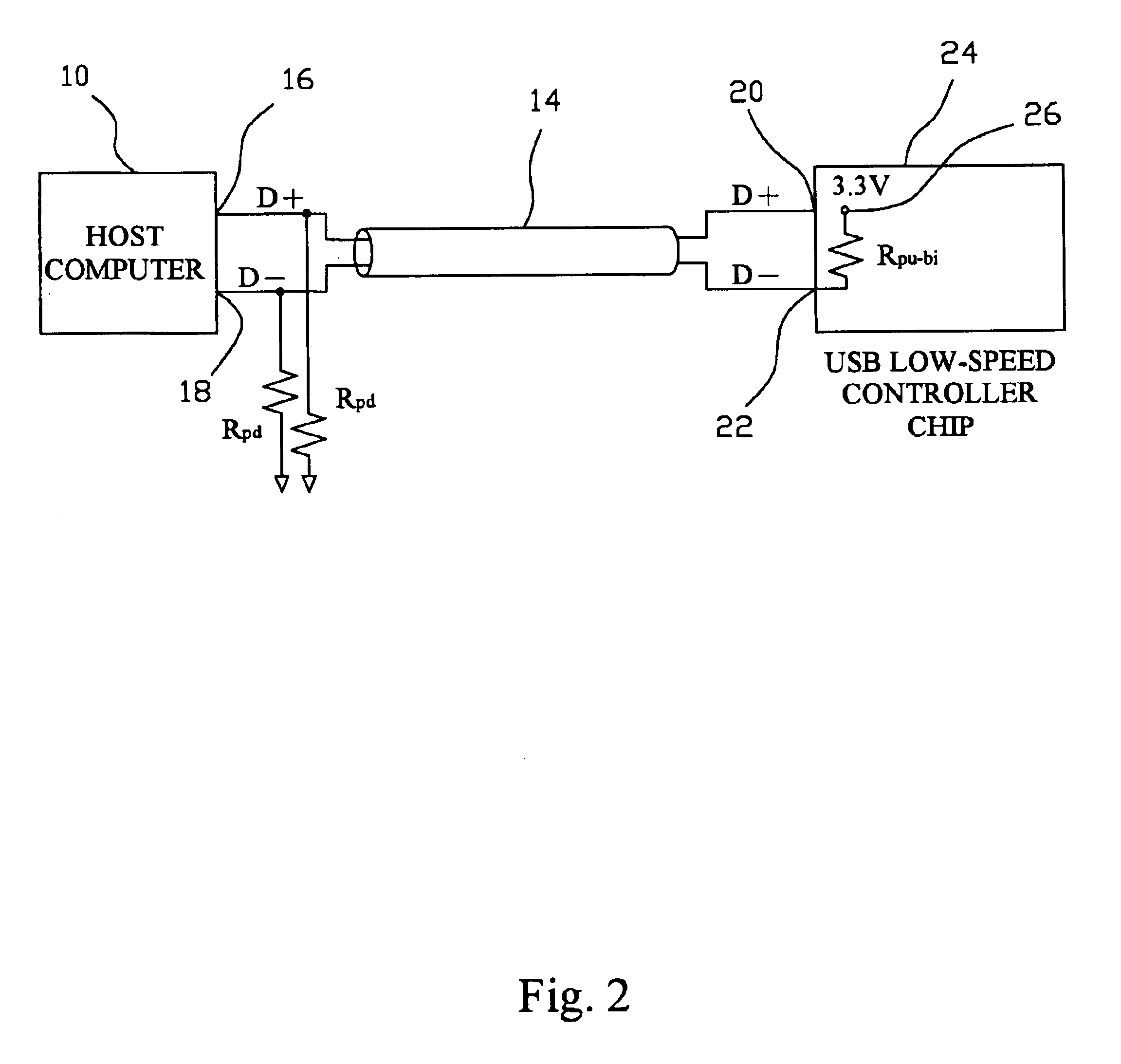
[0011]FIG. 2 shows one embodiment arrangement of the present invention, in which the D+ ports 16 and 20, and D− ports 18 and 22 of the host computer 10 and a USB low-speed device controller chip 24 are connected together by a cable 14 as in the prior art connection, and the USB low-speed device controller chip 24 has a built-in pull-up resistor Rpu-bi of 1.5 KΩ connected between the D− port 22 and a power node 26 connected with a supply voltage of 3.3V, in addition to the pull-down resistors Rpd of 15 KΩ connected from the USB ports 16 and 18, respectively, to ground at the host computer 10 side. However, the tolerance range of the pull-up resistor Rpu-bi could be up to or more than 20%.

[0012]According to the definition in USB specification, a threshold voltage VIH=2.0 V is defined for the USB port, i.e., it is ensured that logic “1” will be determined for the level of the on-line signal by a logical circuit as long as it is larger than 2.0 V. The tolerance range defined by the USB ...


PUM


Abstract

A USB interface controller chip comprises a pair of signal ports for being connecting with a pair of USB signals and a power node for being connecting with a supply voltage characterized in that the controller chip is built-in with a pull-up resistor connected between the power node and one of the pair of signal ports, and the pull-up resistor has a resistance consistent to USB standard but has a tolerance larger than that defined by USB specification.

Description

FIELD OF THE INVENTION[0001]The present invention relates generally to an apparatus for supporting USB interfaces, and more particularly to a USB interface controller chip with a built-in pull-up resistor.BACKGROUND OF THE INVENTION[0002]USB is a standard interface for connections or communications of computer systems with its peripherals, which is divided into low-speed devices and full-speed devices. FIG. 1 illustrates a connection manner of USB low-speed device, of which a host computer 10 and a USB low-speed device controller chip 12 are connected together by a cable 14 with connections of the respective D+ ports 16 and 20, and D− ports 18 and 22. There are two pull-down resistors Rpd of 15 KΩ connected from the D+ and D− ports 16 and 18 to ground, respectively, at the host computer 10 side as well as a pull-up resistor Rpu of 1.5 KΩ connected between the D− signal port 22 and a supply voltage of 3.3 V at the USB low-speed device controller chip 12 side. On the other hand, there...

Claims


Application Information

Patent Timeline
Patent Type & Authority Patents(United States)
IPC IPC(8): G06F13/12G06F13/00G06K7/08G06F13/40
CPCG06F13/4081
Inventor CHIU, YEN-CHANGWU, KAO-PINYEH, TING-HAOLO, MING-CHUAN
Owner ELAN MICROELECTRONICS CORPORATION
Why Eureka
Try Eureka