Oscillation damper with adjustable damping force

a damping force and oscillator technology, applied in the direction of shock absorbers, mechanical equipment, transportation and packaging, etc., can solve the problems of correspondingly high cost, inability to define a small number of angles, and inability to meet the requirements of stepping motors of this kind

Inactive Publication Date: 2005-07-12
ZF SACHS AG
View PDF14 Cites 23 Cited by
  • Summary
  • Abstract
  • Description
  • Claims
  • Application Information

AI Technical Summary

Benefits of technology

[0008]It is an object of the present invention to implement an oscillation damper with an adjustable damping force, in which the problem of the torque peaks that occur has been eliminated, the position of the valve element can be determined in a simple manner and basic setting of the damping force can be implemented in a simple manner.

Problems solved by technology

However, a large adjustment travel is also associated with a more powerful adjusting device, which is correspondingly expensive.
However, to the knowledge of the applicant, stepping motors of this kind are not available in the range of diameters that would be necessary for implementation within a hollow piston rod.
However, it is only possible to define a small number of angles of rotation in this way.
The use of stops to determine the position of a valve element in conjunction with an electric motor involves another problem, which can incidentally also arise if the valve element is embodied as a seat valve that can be moved into the maximum closed position.
When the stop is encountered or the valve seat is occupied, very high impact torques occur, these going far beyond the rated motor torque.

Method used


Image

  • Oscillation damper with adjustable damping force
  • Oscillation damper with adjustable damping force
  • Oscillation damper with adjustable damping force

Examples


Embodiment Construction

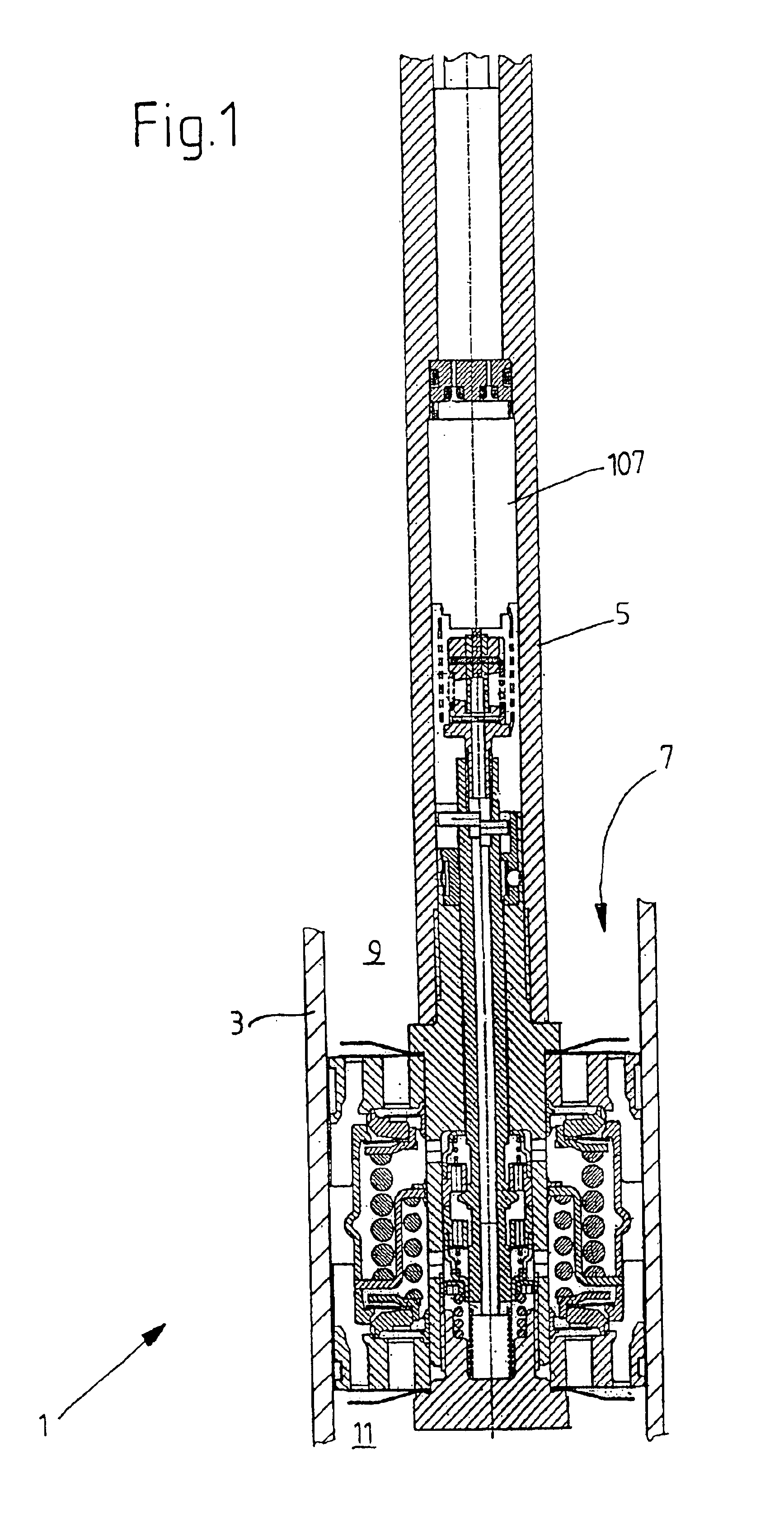
[0035]FIG. 1 shows a fragmentary view of an oscillation damper 1 independently of a specific design, which has an axially movable piston rod 5 in a cylinder 3. Attached to the piston rod is a piston 7, which divides the cylinder, which is filled with a damping medium, into a working space 9 at the piston-rod end and a working space 11 at the opposite end from the piston rod.

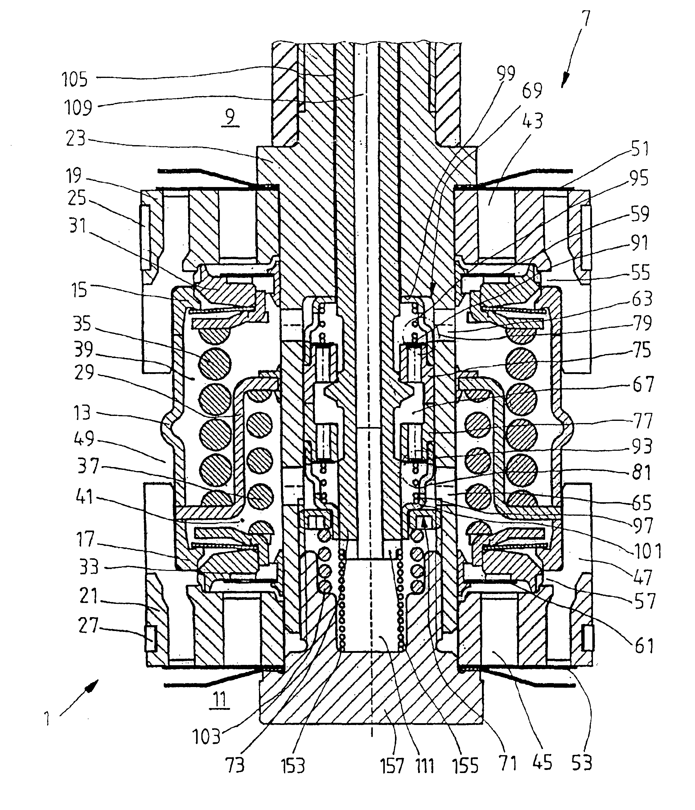
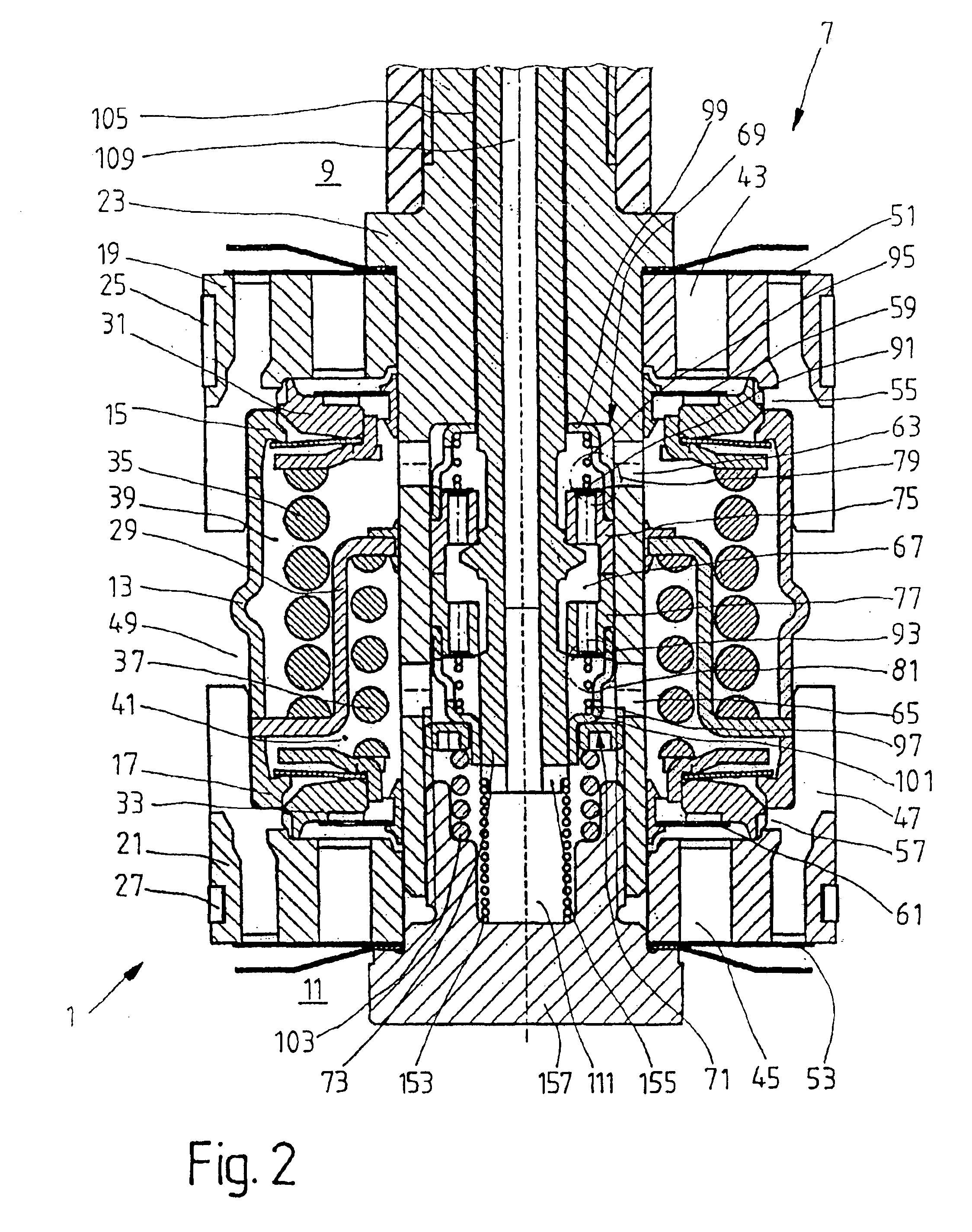
[0036]The piston 7 comprises a central sleeve 13, on the end of which end rings 15; 17 are arranged, these in turn being clamped in firmly in the axial direction on a piston-rod extension 23 by end flanges 19; 21. Both end flanges 19; 21 carry piston rings 25, 27, thus preventing leakage between the piston and the cylinder. Two main-stage valve bodies 31; 33 are clamped between the end flanges 19; 21 and a common dividing sleeve 29 by means of respective valve springs 35; 37. With the piston-rod extension 23, the central sleeve 13 and the end rings 15; 17, the dividing sleeve 29 forms respective separate control ...


PUM


Abstract

Oscillation damper with variable damping force, comprising a valve device, in which an actuator for adjusting the valve device performs a rotary motion against the spring force of a torsion spring, the position of the valve device being determined from the manipulated variable of the actuator and the reaction force of the torsion spring.

Description

BACKGROUND OF THE INVENTION[0001]1. Field of the Invention[0002]The invention relates to an oscillation damper with a variable damping force including a valve device and an actuator for the valve device which performs a rotary motion against the spring force of a torsion spring.[0003]2. Description of the Related Art[0004]Oscillation dampers with a variable damping force achieve a large adjustment range as regards the damping force by having a plurality of valve devices or because an adjusting device can itself cover a large adjustment range. A large adjustment range can be achieved by implementing a significantly large difference in damping force with just a small adjusting movement of the valve device. The difference in damping force generally corresponds to a difference in the cross section of a valve opening. However, relatively high accuracy in the adjustment of the valve device is required for this purpose. If only a small difference in damping force is achieved in relation to...

Claims


Application Information

Patent Timeline
Patent Type & Authority Patents(United States)
IPC IPC(8): F16F9/46F16F9/512F16F9/34F16F9/348F16F9/44F16F9/50F16F9/32
CPCF16F9/3214F16F9/34F16F9/3485F16F9/46F16F9/464F16F9/5126
Inventor FORSTER, ANDREAS
Owner ZF SACHS AG
Why Eureka
Try Eureka