Abrasive belt and machining process associated therewith

a technology of abrasive belts and machining processes, which is applied in the direction of grinding machine components, grinding/polishing apparatuses, grinding machines, etc., can solve the problems of not being able to give the cam surface a very precise machining quality (surface condition) at all, machining a cam surface, and entail a relatively long machining tim

Inactive Publication Date: 2005-07-12
SOC DES PROCEDES & MACHINES SPECIALES
View PDF8 Cites 7 Cited by
  • Summary
  • Abstract
  • Description
  • Claims
  • Application Information

AI Technical Summary

Benefits of technology

[0014]However, according to a preferred embodiment, the two support units each include a fluid jack, the cylinders of the two jacks being mounted on the same carrier in such a way that the axes of the piston rods bearing the support components intersect on the axis of rotation of the part. In this case, the common carrier may be stationary, the jack control alone then making it also possible to obtain the necessary displacements of the support components relative to the bearing surface before and after each machining cycle. Moreover, the jacks enable the support force to be defined with accuracy and particularly kept consistent over the whole circumference of the bearing surface, which is not the case when using springs or similar means.
[0015]The two jacks can be controlled separately, which allows the abrasive belt support force and time spent against the bearing surface by each support component to be adjusted on demand.
[0016]The carrier may additionally carry a belt idler on which the abrasive belt is deflected by being guided transversally between the two support rollers. This allows the abrasive belt which is not guided transversally to its length at the level of the two support rollers to follow better the flapping movements along the axis of the part, movements which are indispensable in superfinishing, as is well known per se.

Problems solved by technology

The same abrasive belt portion is however then sometimes applied, in the cam apex zone, twice in succession against the same surface, i.e., first of all in a new state against a first cam side and then in a “worn” state against a second side of the same cam, which does not make it possible to give to the cam surface a very precise machining quality (surface condition) at all points of the circumference.
In another respect, machining a cam surface by applying a single abrasive belt using a single support roller against this cam surface entails a relatively long machining time.
Applying several abrasive belts using several support rollers against the same cam surface would consequently allow the time taken in machining the cam surface to be reduced, but the result would be to increase the cost—several support units, several abrasive belts, several running (unwinding / winding) abrasive belt systems.
However, this tool and the machine to which it is fitted have a complex structure and a high cost.
In addition, it again has the drawback with respect to inconsistent machining qualities particularly of the two sides of a cam in the cam apex zone.
Furthermore, because of the effect of clamping the cam between the two jaws, this tool does not by definition allow any adjustment of the support pressure exerted by each support roller, which would in certain circumstances be desirable.
Finally, with this tool with four support rollers, only the first roller reached by the abrasive belt applies new abrasive belt against the cam surface, while the other three rollers apply increasingly worn abrasive belt, which reduces their machining effectiveness.

Method used


Image

  • Abrasive belt and machining process associated therewith
  • Abrasive belt and machining process associated therewith
  • Abrasive belt and machining process associated therewith

Examples


Embodiment Construction

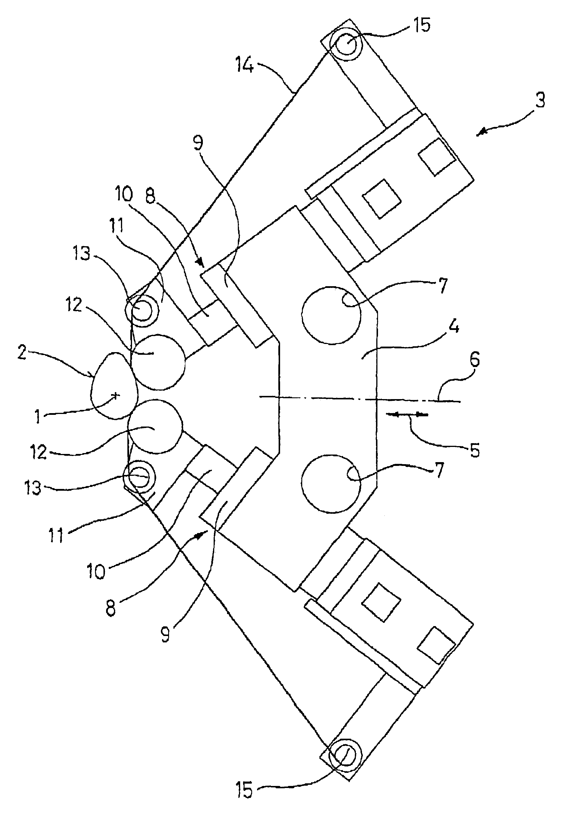
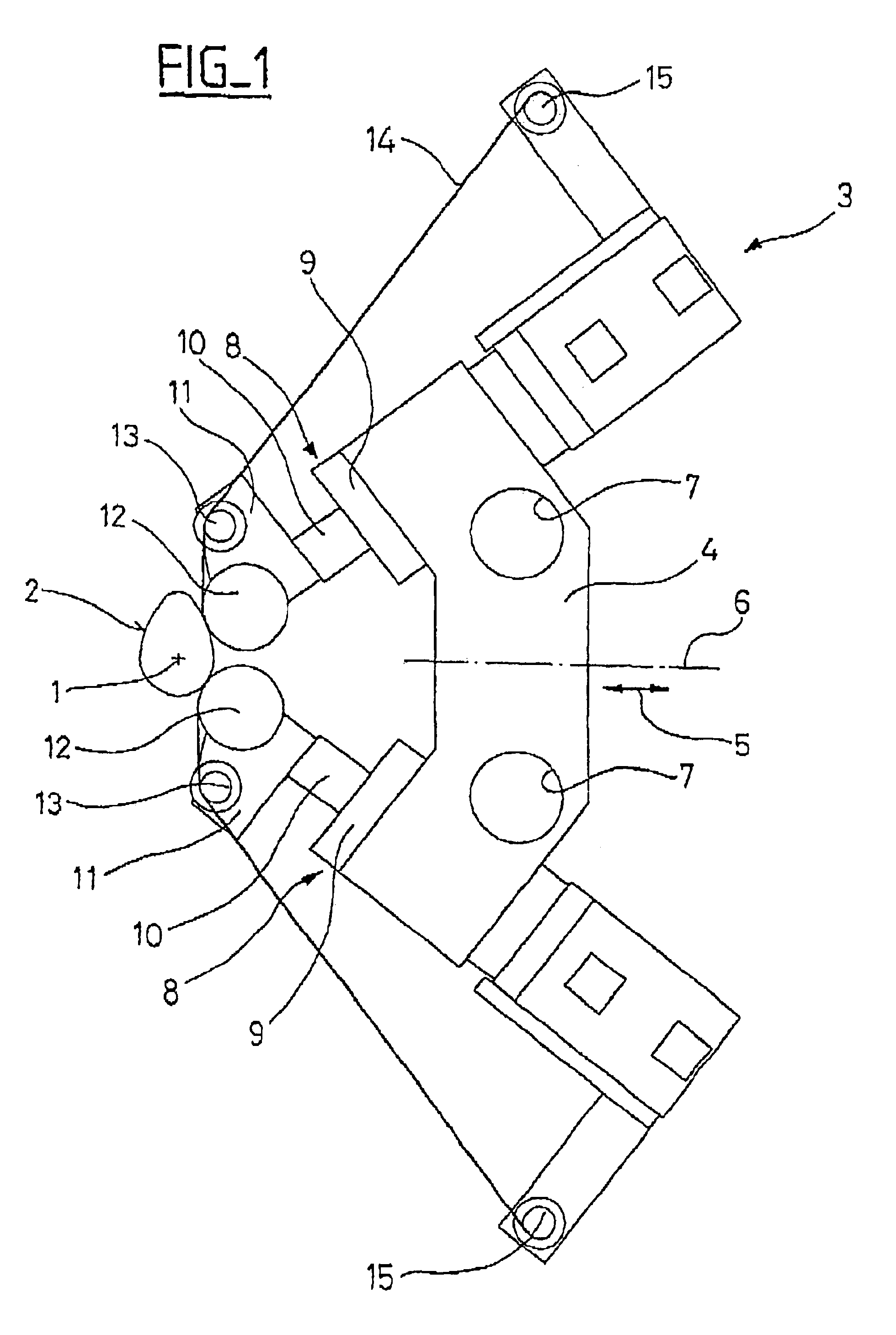
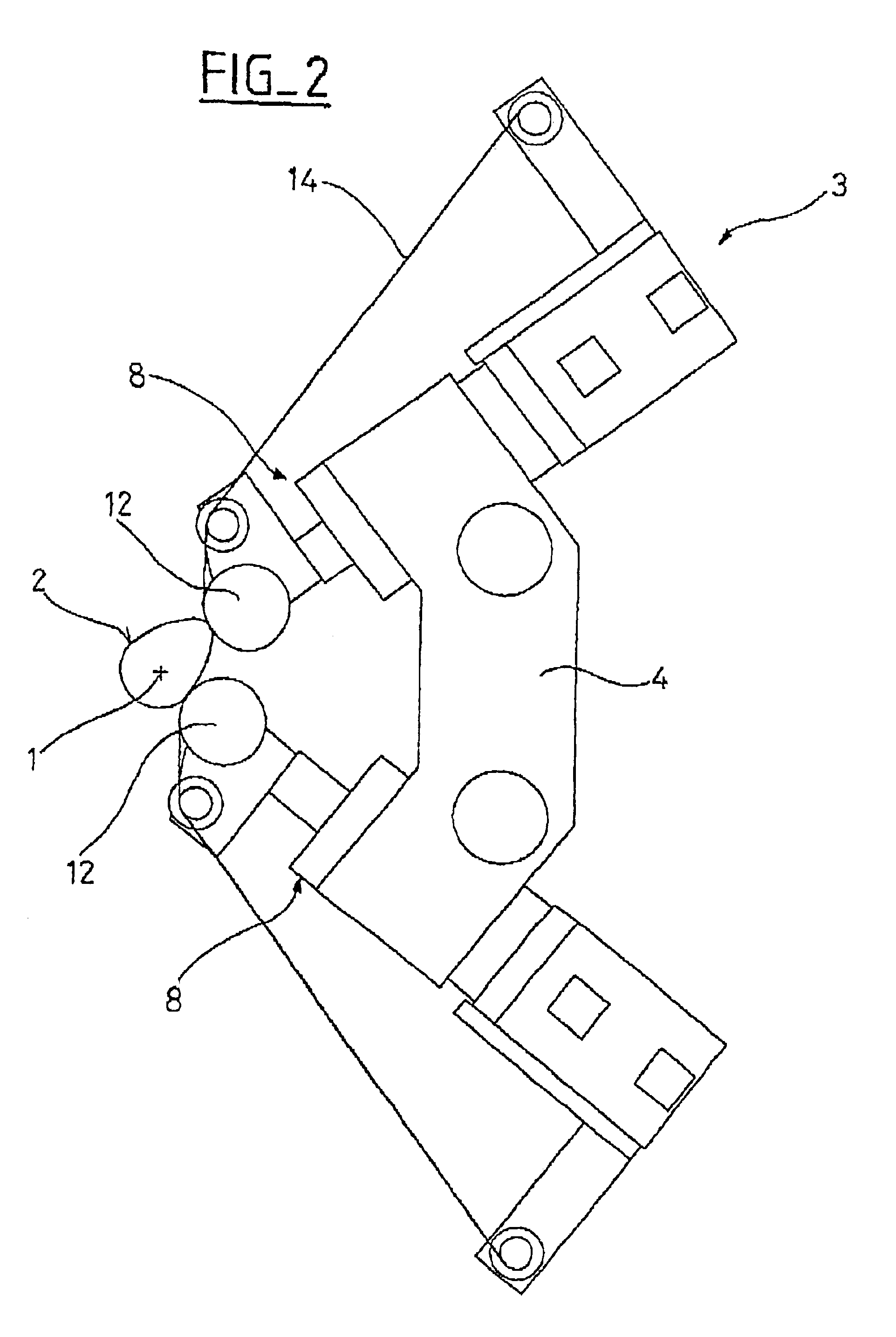
[0020]According to FIG. 1, a camshaft 1 symbolised by its axis of rotation is mounted between centres and driven in rotation around its axis which is here horizontal for the purpose of machining (superfinishing) a cam surface 2 using a device 3 placed on one side of the camshaft 1, approximately in the plane of the cam (surface) 2 to be machined.

[0021]The device 3 includes a carrier 4 mounted, by means not shown, in a position adjustable way (arrow 5) relative to the camshaft 1, along a direction perpendicular to the axis of the latter. For the particular purpose of adapting to different camshafts, the carrier 4 which is symmetrical relative to a plane 6 passing through the axis of the camshaft 1 may furthermore be position adjustable parallel to the axis of the camshaft 1 by guide means which can for example be sockets 7 mobile on sliders.

[0022]The carrier 4 carries, in the same plane perpendicular to its plane of symmetry 6, in symmetrical positions relative to this plane 6, two f...


PUM

PropertyMeasurementUnit
angleaaaaaaaaaa
angleaaaaaaaaaa
angleaaaaaaaaaa

Abstract

A process and device for machining by abrasive belt, on a part 1 with an axis of rotation, of a non-cylindrical bearing surface 2, two portions of the same running abrasive belt 14, which are spaced apart from each other in the longitudinal direction of the belt, using two independent support components 12, preferably activated by two jacks 8 mounted on a common carrier 4, along two contact zones spaced apart angularly around the axis of rotation of the part, are applied against the bearing surface 2. The application is particularly suited for cam surfaces of cam shafts.

Description

BACKGROUND OF THE INVENTION[0001]The present invention relates to a process and a device for the machining by abrasive belt, on a part with an axis of rotation, of at least one non-cylindrical bearing surface, particularly for superfinishing a cam surface on a cam shaft.DESCRIPTION OF THE RELATED ART[0002]Superfinishing by abrasive belt, commonly called superfinishing by “polishing”, of cam surfaces on camshafts may be carried out, with the camshaft mounted between centres and driven in rotation around an axis, by applying a running abrasive belt against a cam surface using a support roller pushed against said cam surface by a jack. The same abrasive belt portion is however then sometimes applied, in the cam apex zone, twice in succession against the same surface, i.e., first of all in a new state against a first cam side and then in a “worn” state against a second side of the same cam, which does not make it possible to give to the cam surface a very precise machining quality (surf...

Claims


Application Information

Patent Timeline
Patent Type & Authority Patents(United States)
IPC IPC(8): B24B19/00B24B21/00B24B19/12B24B49/16
CPCB24B19/12B24B21/004B24B49/16
Inventor BONACHERA, RICHARDMILLOT, RAYMOND
Owner SOC DES PROCEDES & MACHINES SPECIALES
Why Eureka
Try Eureka