Li-ion/Li-polymer battery charger configured to be DC-powered from multiple types of wall adapters

a technology of lithium-ion and lithium-polymer batteries, which is applied in the direction of electric power, electric vehicles, transportation and packaging, etc., can solve the problem of not being able to provide that amount of current, and achieve the effect of reducing dissipation and faster recharg

Inactive Publication Date: 2005-07-12
INTERSIL INC
View PDF10 Cites 21 Cited by
  • Summary
  • Abstract
  • Description
  • Claims
  • Application Information

AI Technical Summary

Benefits of technology

[0014]Upon initialization of the fast charge mode, the charge controller will demand the full current limit set by the controller but will not be able to provide that amount of current because the external adapter is current limited to a value less than the controller-set level. The controller will therefore turn on its control pass element (such as a MOSFET) to minimize the resistance between the adapter output and the battery that is being charged, thereby forcing the adapter to enter its current limit state and consequently bringing its voltage very close to the battery voltage. It maintains that reduced voltage level while sustaining the current limit condition.
[0017]If the temperature of the controller rises to a prescribed threshold it will begin decreasing the charge current to lower the dissipation and therefore the temperature. This assures that the controller does not abruptly interrupt the charge, as is characteristic of more conventional controller types, but simply moderates the charge rate to a thermally manageable level. This hybrid charging protocol of the present invention yields recharge times comparable to a pulse mode controller and typically faster recharge than a simple constant voltage adapter protocol with the same current limits.

Problems solved by technology

Upon initialization of the fast charge mode, the charge controller will demand the full current limit set by the controller but will not be able to provide that amount of current because the external adapter is current limited to a value less than the controller-set level.

Method used


Image

  • Li-ion/Li-polymer battery charger configured to be DC-powered from multiple types of wall adapters
  • Li-ion/Li-polymer battery charger configured to be DC-powered from multiple types of wall adapters
  • Li-ion/Li-polymer battery charger configured to be DC-powered from multiple types of wall adapters

Examples


Embodiment Construction

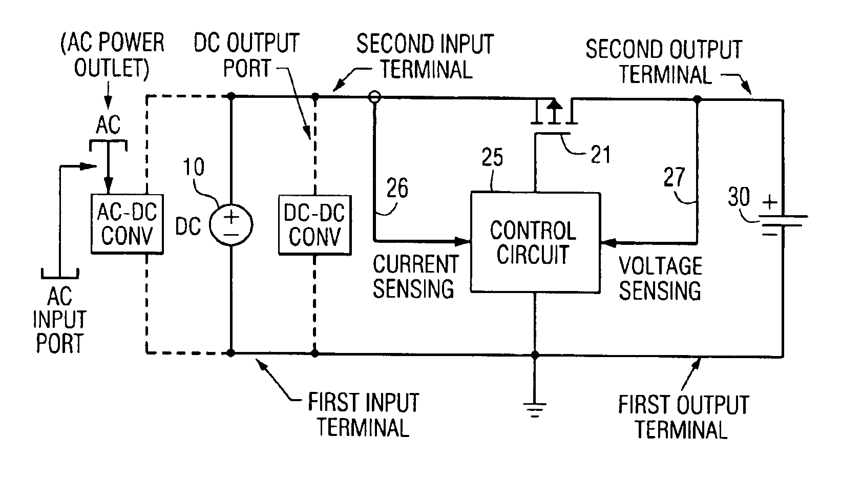
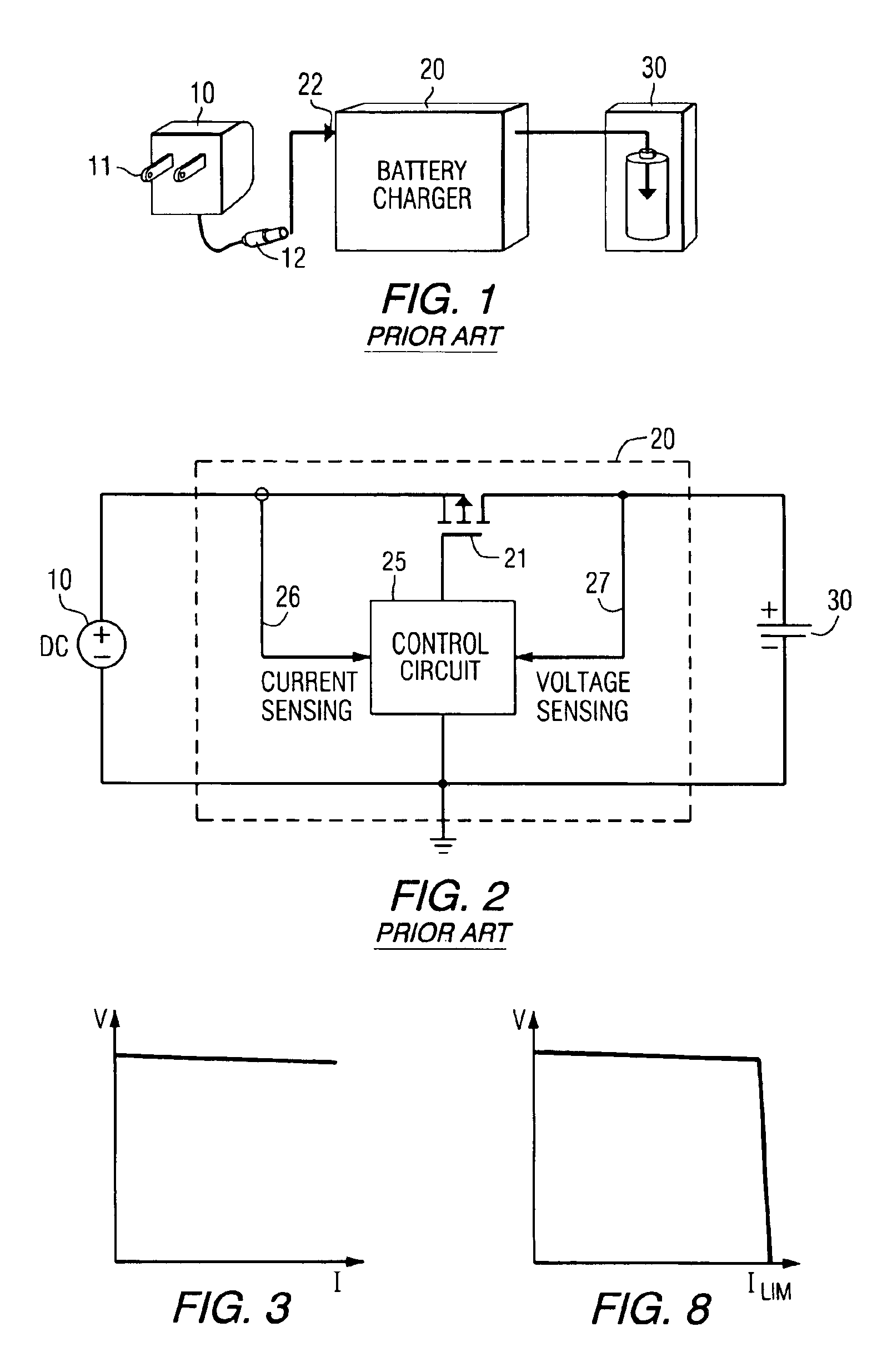
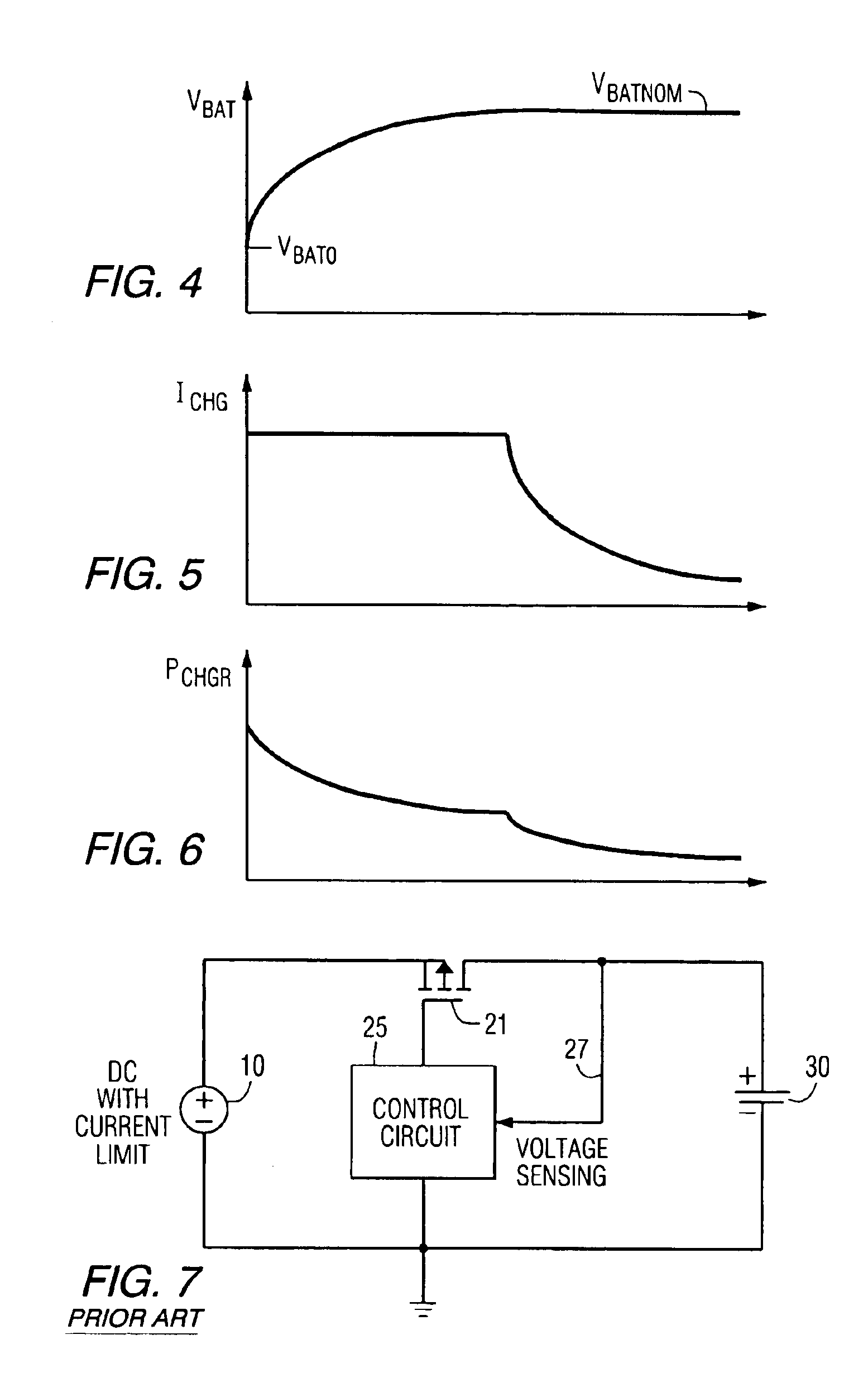
[0033]Before describing the multi-adapter compatible battery charger in accordance with the invention, it should be observed that the invention resides primarily in an arrangement of conventional DC power supply circuits and control components integrated together. It is to be understood that the invention may be embodied in a variety of implementations, and should not be construed as being limited to only those shown and described herein. For example, although the non-limiting circuit diagrams of the Figures shows the use of MOSFET devices to perform controlled current path operations, it will be appreciated that the invention is not limited thereto, but also may be configured of alternative equivalent circuit devices, such as, bipolar transistors. The implementation example to be described is intended to furnish only those specifics that are pertinent to the present invention, so as not to obscure the disclosure with details that are readily apparent to one skilled in the art havin...


PUM


Abstract

A battery charger controller is coupled to DC output terminals of an AC-DC (or DC-DC) adapter containing an AC-DC (or DC-DC) converter. A controlled current flow path between input and output terminals of the battery charger controller circuit is controlled to provide a substantially constant current to charge the battery to a nominal battery voltage. When a constant voltage output of the said adapter transitions to a value that limits available charging current to a value less than programmed constant charging current, current flow drive for the controlled current flow path is increased for a limited time interval. Thereafter, the controlled current flow path gradually reduces charging current as the battery voltage remains at its nominal battery voltage until the charge is complete or otherwise terminated.

Description

CROSS-REFERENCE TO RELATED APPLICATION[0001]The present application is a continuation application of U.S. patent application Ser. No. 10 / 314,543, filed on Dec. 9, 2002, entitled “Li-Ion / Li-Polymer Battery Charger Configured To Be DC-Powered From Multiple Types Of Wall Adapters”, by Lai et al, now U.S. Pat. No. 6,844,705, assigned to the assignee of the present application, and the disclosure of which is incorporated herein.FIELD OF THE INVENTION[0002]The present invention relates, in general, to battery chargers, including those used for charging DC batteries / cells, such as, but not limited to, Li-ion / Li-polymer batteries of the type used to power portable electronic devices, such as laptop / notebook computers, personal digital assistants (PDAs), and the like, and is particularly directed to a new and improved battery charger controller architecture having ‘plug-in’ compatibility with various types of power adapters, while providing substantially reduced thermal dissipation.BACKGROUN...

Claims


Application Information

Patent Timeline
Patent Type & Authority Patents(United States)
IPC IPC(8): H02J7/00
CPCH02J7/0055H02J7/0093H02J7/0073H02J7/0071H02J7/00711H02J2207/40H02J7/00H02J7/02
Inventor LAI, ZHERENBORDEAUX, EDWARDWU, ZEN
Owner INTERSIL INC
Why Eureka
Try Eureka