Fully integrated automatically-tuned RF and IF active bandpass filters

a filter and fully integrated technology, applied in waveguide type devices, transmission, line-transmission details, etc., can solve the problem of 40 db attenuation of the first bp reference, and achieve the effect of good linearity and sufficient attenuation

Inactive Publication Date: 2005-07-12
WYSZYNSKI ADAM S
View PDF32 Cites 26 Cited by
  • Summary
  • Abstract
  • Description
  • Claims
  • Application Information

AI Technical Summary

Benefits of technology

[0015]The present automatic tuning scheme for two BP filters is used in a fully-integrated heterodyne receiver such as one in FIG. 7. Contrary to other tuning schemes both filters operate on the signal while simultaneously being tuned using a reference signal. To allow that the amplitude of reference signal is made small and since both filters demonstrate a good linearity the build-up of the inter-modulation distortion does not occur. For accuracy reasons the first BP is tuned with the reference falling into its pass-band. Under such conditions the reference is not practically attenuated by the first BP filter. However the same distance between the pass-band center and the reference frequency in the second BP filter results in about 40 dB attenuation of the first BP reference. This is because the second BP bandwidth is much narrower than the first BP center bandwidth. At lower IF frequency its order and its Q's can be made sufficiently high to achieve sufficient attenuation. This combined with at least 15 dB the original signal-to-reference ratio results in the desired 55 dB the final signal-to-reference ratio. However, the second band-pass is also tuned. Since there is no further filter in the signal path its tuning reference cannot be removed. To solve this problem the complexity of the second BP is exploited. Assuming the filter passes the signal for positive frequencies if the reference is made a negative frequency by appropriate 90 degrees phase shifting it will be attenuated by at least 55 dB, which is a sufficient signal-to-reference ratio.

Problems solved by technology

However the same distance between the pass-band center and the reference frequency in the second BP filter results in about 40 dB attenuation of the first BP reference.

Method used


Image

  • Fully integrated automatically-tuned RF and IF active bandpass filters
  • Fully integrated automatically-tuned RF and IF active bandpass filters
  • Fully integrated automatically-tuned RF and IF active bandpass filters

Examples


Embodiment Construction

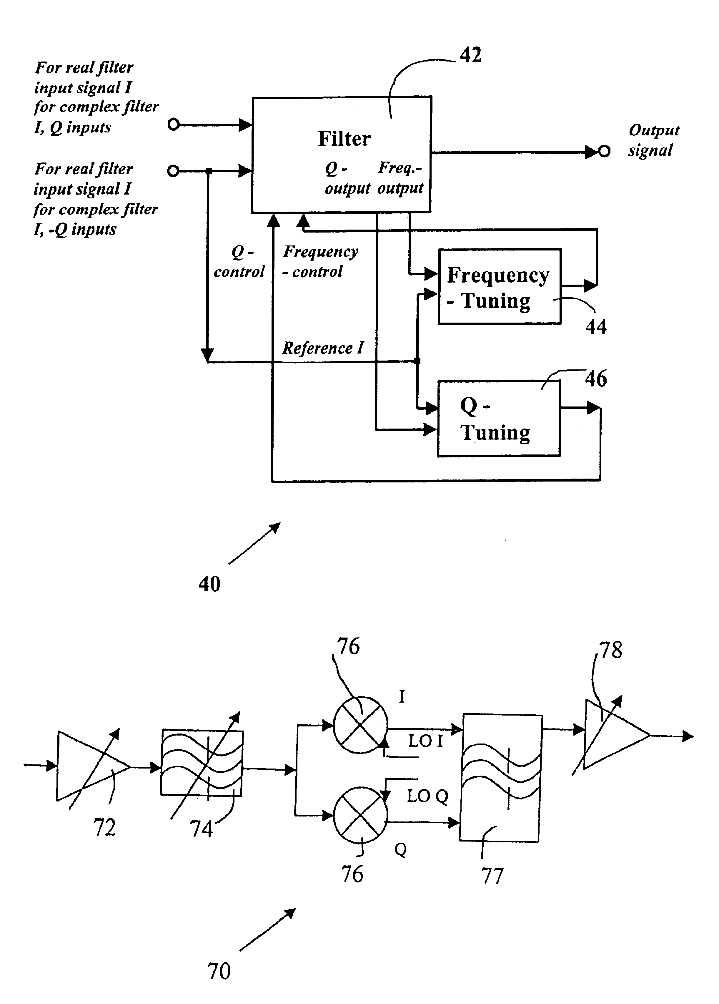
[0023]Referring to the FIG. 4, the present automatically-tuned filter system is illustrated, and is generally identified by the numeral 40. The input signal enters the filter circuit 42, one of the filter outputs is connected to the frequency-tuning block 44 and the other one is connected to the Q-tuning block 46. The output of the frequency-tuning block 44 is then fed back to the filter 42 in order to control its frequency. Similarly, the output of the Q-tuning block 46 is then fed back to the filter 42 in order to control its Q.

[0024]The output of the filter 42 may also serve as a frequency- and / or Q-tuning output. In such a case the original frequency- or Q-tuning output(s) is (are) redundant and is (are) not used.

[0025]If the filter circuit 42 is a real band-pass filter such as filter 74 illustrated in FIG. 7 the reference is placed at frequency f2 that is offset from the filter center frequency f1 by Δf=f2−f1. This situation is illustrated in FIG. 5a. Since the reference passes...


PUM


Abstract

An automatic tuning scheme for two active band-pass filters where both filters operate on the signal while simultaneously being tuned using a reference signal. To allow that the amplitude of a reference signal is made small and since both filters demonstrate a good linearity the build-up of the inter-modulation distortion does not occur. The first band-pass filter is tuned with the reference falling into its pass-band. The second band-pass filter is also tuned with the reference placed into its pass-band. The reference is practically eliminated by the virtue of the complexity of the second band-pass filter. Assuming the filter passes the signal for positive frequencies if the reference is made a negative frequency by appropriate 90 degrees phase shifting it will be attenuated by at least 55 dB, which is a sufficient signal-to-reference ratio.

Description

TECHNICAL FIELD OF THE INVENTION[0001]The present invention relates to fully-integrated continuous-time active band-pass filters and their automatic frequency- and Q-tuning systems.BACKGROUND OF THE INVENTION[0002]Nearly all practical transceivers require some form of filtering. Up to the date, in majority of cases, these radio-frequency (RF) and intermediate-frequency (IF) filters are realized off-chip as ceramic or surface-acoustic wave (SAW) devices.[0003]A first reason for slow progress in integration RF and IF filters is their rather modest noise and distortion performance. This can be alleviated by a careful overall system design by taking into account the filter short comings and by purposely reducing their requirements while simultaneously offsetting their reduced performance with superior performance of preceding and following high-quality blocks.[0004]A second reason for slow progress in integration RF and IF filters is that these filters require circuitry for adjusting th...

Claims


Application Information

Patent Timeline
Patent Type & Authority Patents(United States)
IPC IPC(8): H04B3/04H03J3/08
CPCH03J3/08H03J2200/08H03J2200/18
Inventor WYSZYNSKI, ADAM S.
Owner WYSZYNSKI ADAM S
Why Eureka
Try Eureka