System and method for in-system programming through an on-system JTAG bridge of programmable logic devices on multiple circuit boards of a system

a programmable logic and system technology, applied in the direction of computation using denominational number representation, pulse technique, instruments, etc., can solve the problems of large system size, difficulty in prior configuration process, and inability to provide configuration code information

Inactive Publication Date: 2005-07-12
HEWLETT-PACKARD ENTERPRISE DEV LP +1
View PDF48 Cites 34 Cited by
  • Summary
  • Abstract
  • Description
  • Claims
  • Application Information

AI Technical Summary

Benefits of technology

[0025]The present invention is a system having multiple, interconnected circuit boards, of which more than one has at least one EEPROM coupled to provide configuration code to an FPGA. The EEPROM devices of each such board are coupled into a JTAG chain, with a separate chain for each such board. The JTAG chains from each such board are routed to a common configuration logic block. The common configuration logic block provides an interface between the multiple JTAG chains and a processor of the system, as well as selection circuitry such that the processor may address individual JTAG chains of the multiple JTAG chains.

Problems solved by technology

These FPGAs generate an error signal when the checksum verification fails, indicating that their configuration code might not be correct.
While loading FPGA configuration code into EEPROMs of a board works well for small systems, it can pose difficulties with large systems.
The prior configuration process also poses difficulties when separate JTAG chains are used to load FPGA configuration code into EEPROMs of each board of a large system.
For example, the multiple circuit boards of large systems are often not readily accessible for coupling of a configuration system to a configuration header without removing them from the system.
Physical access to a system by a technician also may require travel expense.
In either case, substantial labor and system downtime may be required to update the FPGA configuration codes of all boards of a large system.

Method used


Image

  • System and method for in-system programming through an on-system JTAG bridge of programmable logic devices on multiple circuit boards of a system
  • System and method for in-system programming through an on-system JTAG bridge of programmable logic devices on multiple circuit boards of a system
  • System and method for in-system programming through an on-system JTAG bridge of programmable logic devices on multiple circuit boards of a system

Examples


Embodiment Construction

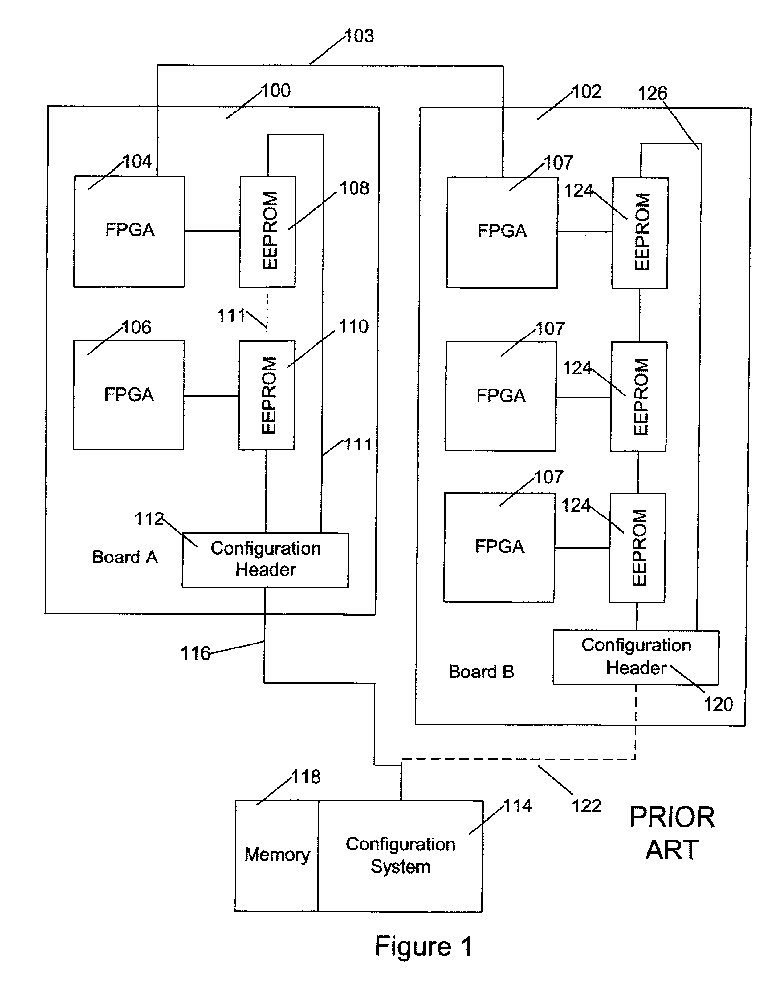
[0041]A computer system as known in the art incorporates multiple circuit boards, such as Board A 100 (FIG. 1) and Board B 102 embodying FPGAs 104, 106, 107 on the boards. There may be additional boards in the system, both with and without FPGAs, the various boards being coupled together 103 as components of the system. On Board A 100, FPGA 104 is coupled to a configuration EEPROM 108, such that FPGA 104 receives its configuration code from EEPROM 108 when Board A 100 is powered-up. Similarly, FPGA 106 is coupled to a second configuration EEPROM 110. Configuration EEPROMs 108 and 110 are chained together in a JTAG chain 111 that is brought out to a configuration header 112.

[0042]When it is desired to update configuration code of one or more of the FPGAs 104 or 106 on Board A 100, a configuration system 114 is coupled through a configuration cable 116 to configuration header 112. Configuration code may then be transferred from a memory system 118 of configuration system 114 through c...


PUM


Abstract

A system, such as a complex computer system, incorporates several programmable logic devices coupled to load their configuration code from associated EEPROMs; typically this load is automatic on powerup. The EEPROMs connect to one of several serial busses, typically JTAG busses, connecting the EEPROMs with a common configuration logic. A processor is configured to write programmable logic configuration code from its memory through the common configuration logic and over the serial busses into the EEPROMs. The processor is also capable of connecting to a network and fetching configuration code for writing to the EEPROMs.

Description

RELATED APPLICATIONS[0001]This application is related to copending and cofiled applications for U.S. Pat. Ser. No. 09 / 918,023, filed Jul. 30, 2001 and entitled METHOD AND APPARATUS FOR IN-SYSTEM PROGRAMMING THROUGH A COMMON CONNECTION POINT OF PROGRAMMABLE LOGIC DEVICES ON MULTIPLE CIRCUIT BOARDS OF A SYSTEM Ser. No. 09 / 918,030, filed Jul. 30, 2001 and entitled FIRMWARE FOR ACCESSING SCAN CHAINS AND UPDATING EEPROM-RESIDENT FPGA CODE VIA A MANAGEMENT BUS TO JTAG BUS BRIDGE; Ser. No. 09 / 718,024 filed Jul. 30, 2001 and entitled METHOD AND APPARATUS FOR SERIAL BUS TO JTAG BUS BRIDGE; and Ser. No. 09 / 917,982, filed Jul. 30, 2001 and entitled METHOD FOR JUST-N-TIME UPDATING OF PROGRAMMING PARTS, all of the aforementioned applications incorporated herewith by reference thereto.FIELD OF THE INVENTION[0002]The invention is related to the art of providing configuration code information to programmable logic devices, including Field Programmable Gate Array (FPGA) devices in complex electronic...

Claims


Application Information

Patent Timeline
Patent Type & Authority Patents(United States)
IPC IPC(8): G06F15/76G06F15/78G06F11/00
CPCG06F15/7867
Inventor MANTEY, PAULERICKSON, MIKEMACIOROWSKI, DAVID
Owner HEWLETT-PACKARD ENTERPRISE DEV LP
Why Eureka
Try Eureka