
Dunnage converter system

Active Publication Date: 2005-07-19
RANPAK CORP
View PDF16 Cites 39 Cited by
  • Summary
  • Abstract
  • Description
  • Claims
  • Application Information

AI Technical Summary

Benefits of technology

[0008]The present invention provides a packaging system which provides easy access to components thereof. According to one general aspect of the invention, a stand guides sheet stock material to a dunnage conversion machine. According to another aspect of the invention, an infeed paper guide assembly of a dunnage conversion machine guides sheet stock material from a stock supply and through the dunnage conversion machine. According to a further general aspect of the invention, a pulling assembly motor and severing assembly motor are disposed in an L-shape configuration to support a dunnage conversion machine having a compact configuration.
[0035]According another aspect of the invention, there is provided a method of converting sheet material into a dunnage product. The method includes the steps of using a pulling assembly for advancing the sheet material through the machine; wherein the step of advancing the sheet material includes moving grippers together through a transfer region in opposition to one another to cooperatively grip therebetween the sheet material and advance the sheet material through the transfer region, while an aperture in at least one of the grippers gathers and laterally captures therein the sheet material as the grippers are moved through the transfer region; further including ramping the speed of the pulling assembly up before starting a conversion process.
[0036]According another aspect of the invention, there is provided a method of converting sheet material into a dunnage product. The method includes the steps of using a pulling assembly for advancing the sheet material through the machine; wherein the step of advancing the sheet material includes moving grippers together through a transfer region in opposition to one another to cooperatively grip therebetween the sheet material and advance the sheet material through the transfer region, while an aperture in at least one of the grippers gathers and laterally captures therein the sheet material as the grippers are moved through the transfer region; further including ramping the speed of the pulling assembly down after a conversion process is completed.

Problems solved by technology

Although the sheet stock material usually follows a consistent path as it travels from the supply to the upstream end of the machine, when the conversion machine is operating at relatively high speeds, for example, as when a void fill product is being produced, or during starting and stopping of the machine, the sheet stock material may experience ripples or undulations.
Sometimes, these undulations may initiate a tear in a lateral edge portion of the sheet stock material, possibly causing a machine jam or deleterious effects in the quality of the dunnage product.
Other machines are constructed in such a manner that access to components inside the machine, for example for assembly or servicing of the components, is hindered by the particular orientation of the machine or the complexity of the mounting arrangement of the components therein.

Method used


Image

  • Dunnage converter system
  • Dunnage converter system
  • Dunnage converter system

Examples


Embodiment Construction

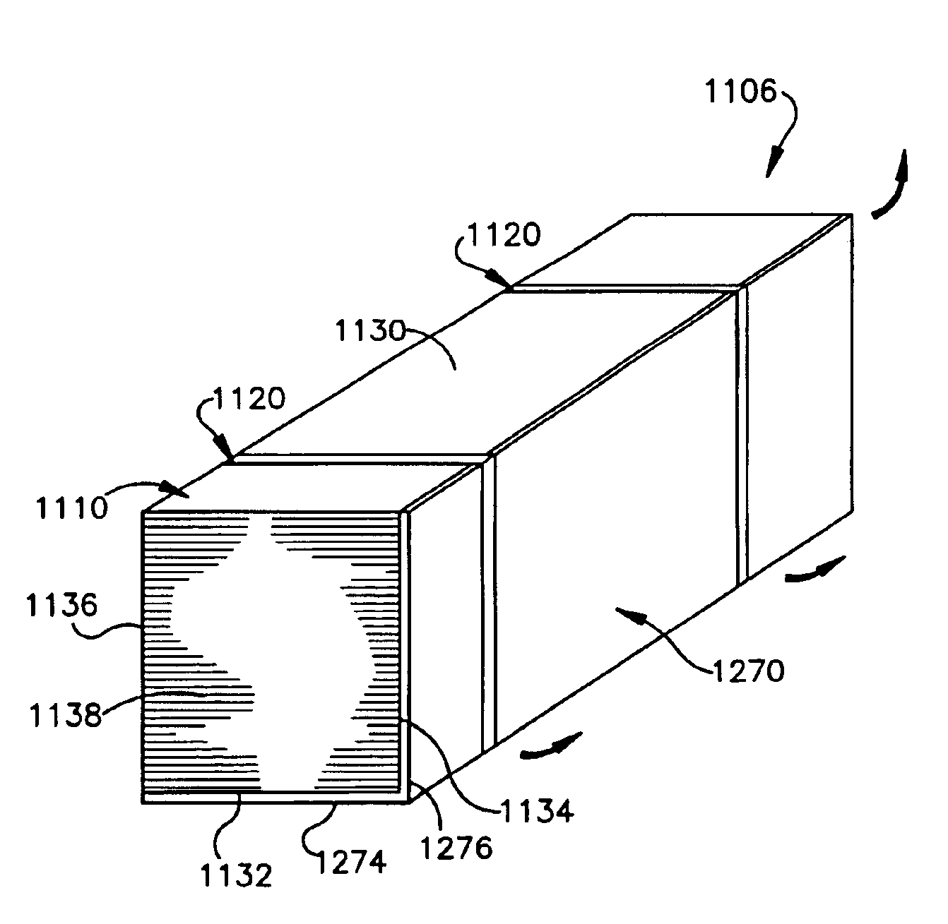
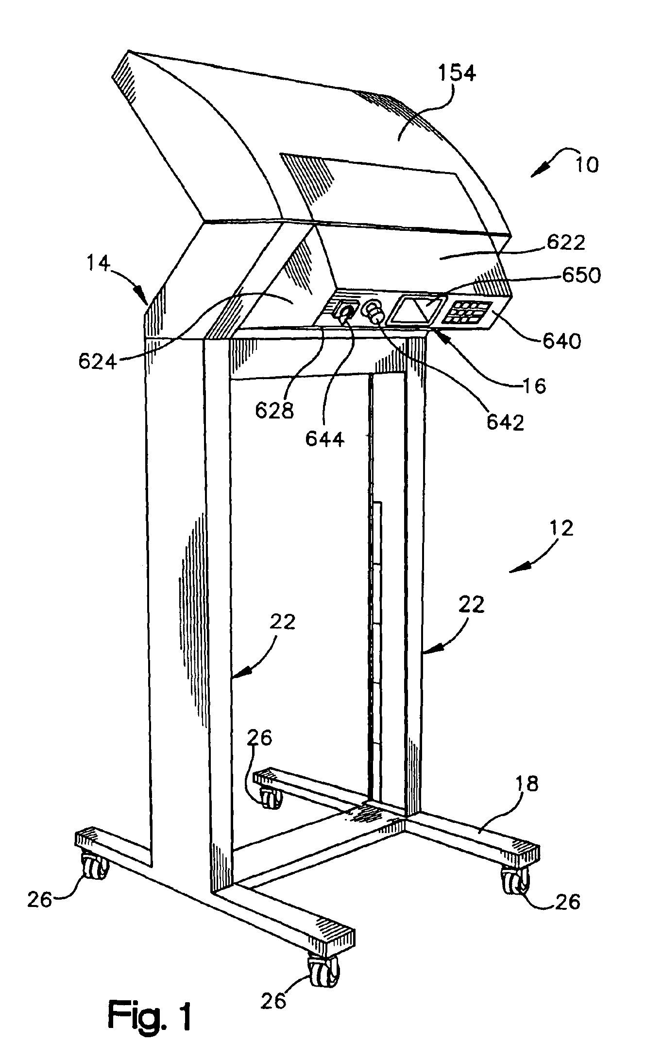
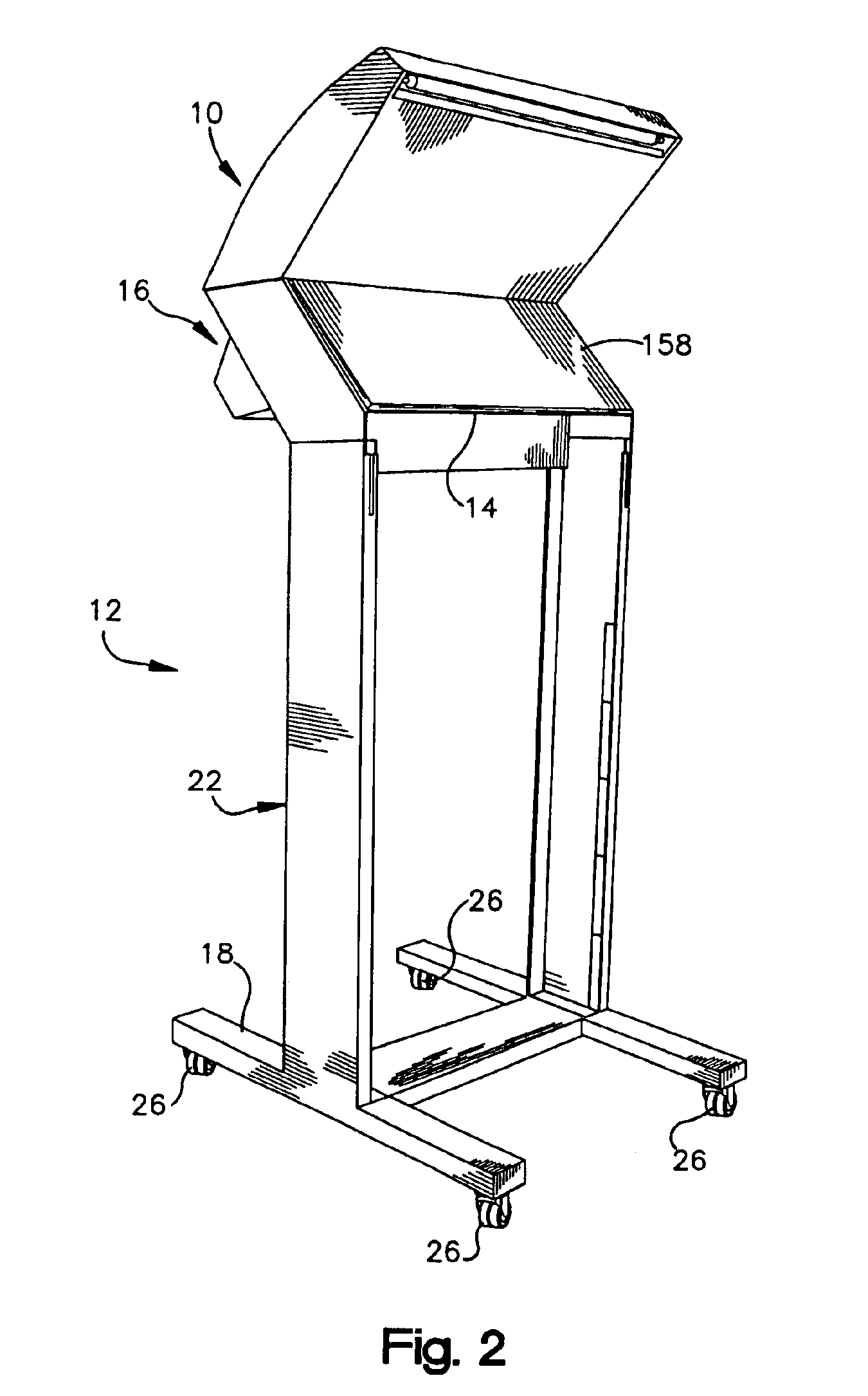
[0088]Referring now to the drawings in detail and initially to FIGS. 1 to 4, there is shown a dunnage conversion machine 10 and a stand 12 in accordance with the present invention. The dunnage conversion machine 10 converts a sheet-like stock material, such as one or more layers of recyclable and reusable Kraft paper, into a strip of dunnage including, for example, a relatively narrow three dimensional strip or rope of a generally cylindrical shape. The machine 10 has an upstream end 14 at which sheet stock material is supplied to the machine 10, and a downstream end 16 from which the machine 10 discharges dunnage product. As used herein, the terms upstream and downstream refer to a travel path of sheet stock material, illustrated at 15 (FIG. 8), as it passes from the stand 12 to the outlet of the dunnage conversion machine 10 as a strip of dunnage product. The dunnage product is used as an environmentally responsible protective packaging material typically used as void fill or cush...


PUM

PropertyMeasurementUnit
Dimensionaaaaaaaaaa

Abstract

An easy load packaging system, and a stand and a dunnage conversion machine therefor are disclosed. The stand includes a base and a pair of upright guide members mounted to the base and supporting at the upper ends thereof a dunnage conversion machine. The guide members define there between a channel for guiding sheet stock material to the dunnage conversion machine. The dunnage conversion machine is pivotable relative to the stand between an operating position and a servicing / loading position whereat access to internal components of the machine is simplified. A stack of sheet stock material is jacketed and / or baled for simplified loading into a packaging system or stand. An adhesive layer on the bottom or top of the stack enables the stack to be easily spliced to another stack.

Description

RELATED APPLICATION DATA[0001]This application claims the benefit under 35 USC 119(e) of earlier filed U.S. Provisional Application Nos. 60 / 433,548, filed on Dec. 13, 2002; 60 / 421,996, filed on Oct. 29, 2002; 60 / 412,127, filed on Sep. 18, 2002; and 60 / 375,149, filed on Apr. 22, 2002, all of which are hereby incorporated herein by reference in their entireties.FIELD OF THE INVENTION[0002]The present invention relates to a dunnage converter and, more particularly, to a dunnage converter and fan folded stock material therefor that enable improved loading ability of the stock material.BACKGROUND OF THE INVENTION[0003]Cushioning conversion machines convert sheet stock material into a relatively more dense strip of dunnage product which is useful in providing cushioning in packages. Typically, a conversion machine is mounted to a stand so that the conversion machine is at a height at which dunnage product produced by the machine may be easily accessed, for example, at eye level of the ope...

Claims


Application Information

Patent Timeline
IPC IPC(8): B31D5/00
CPCB31D5/0047B65D75/56B65D75/566B65D75/5827B65D71/02B31D2205/0035B31D2205/0047B31D2205/0082Y10T428/24686Y10S493/904
Inventor HARDING, JOSEPH J.SKIBA, JUDITH L.SIMMONS, JR., JAMES A.TEKAVEC, JAMESLINTALA, EDWARD W.METHORST, ERWINKUYPERS, KOEN H. M.COPPUS, DANCHEICH, ROBERTDEMERS, RAYMOND P. M.KOBBEN, PIERRE
Owner RANPAK CORP
Learn More