Ultrasound diagnostic apparatus

a diagnostic apparatus and ultrasonic technology, applied in the field of ultrasonic diagnostic apparatus, can solve the problems of contrast agent instantaneously collapsing upon ultrasound wave application, microbubbles on adjacent scanning lines rapidly shrinking and collapsing,

Inactive Publication Date: 2005-07-19
KK TOSHIBA
View PDF14 Cites 46 Cited by
  • Summary
  • Abstract
  • Description
  • Claims
  • Application Information

AI Technical Summary

Benefits of technology

[0018]It is an object of the present invention to allow an ultrasound diagnostic apparatus to exhibit a contrast enhance effect based on an ultrasound contrast agent within a slice as uniformly as possible.

Problems solved by technology

Microbubbles rapidly shrink and collapse upon reception of strong ultrasound waves.
That a contrast agent instantaneously collapses upon application of ultrasound waves is the most serious problem in the contrast echo method.
In practice, however, since an ultrasound beam has a certain width, most microbubbles on the adjacent scanning line collapse in many cases.
In addition, ultrasound waves greatly attenuate because of the long propagation distance.
As a consequence, microbubbles on adjacent ultrasound scanning lines collapse.
When, therefore, ultrasound transmission / reception is performed afterward in this scanning line direction, microbubbles will have collapsed and been lost.
However, a response of microbubbles exhibits strong nonlinearity, and phenomena such as nonlinear vibrations, expansion, and collapse of microbubbles, vary in a complicated manner depending on the absolute level of applied sound pressure.
Therefore, it is practically impossible to correct reception signals.

Method used


Image

  • Ultrasound diagnostic apparatus
  • Ultrasound diagnostic apparatus
  • Ultrasound diagnostic apparatus

Examples


first embodiment

(First Embodiment)

(Arrangement and Flow of Signals)

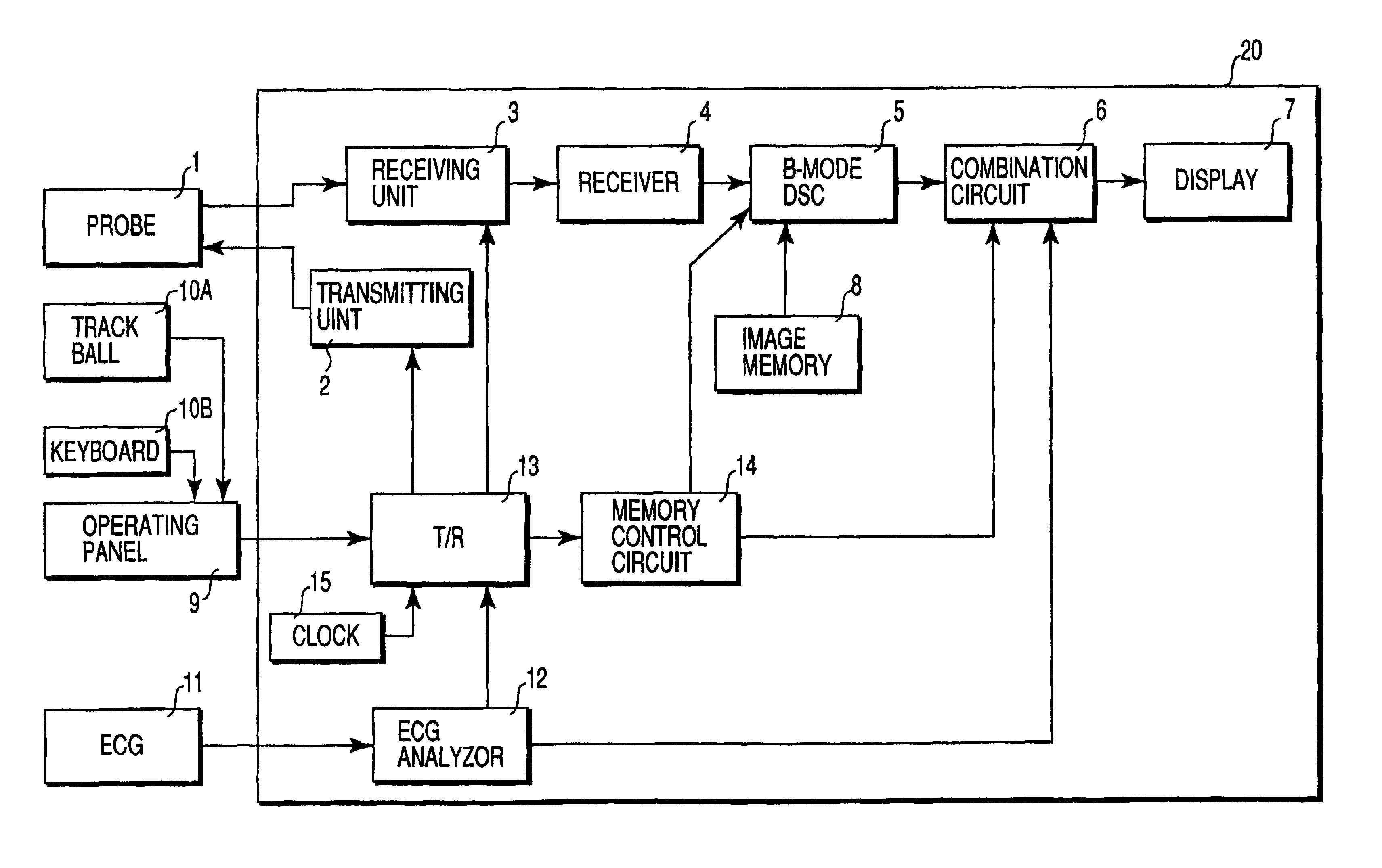
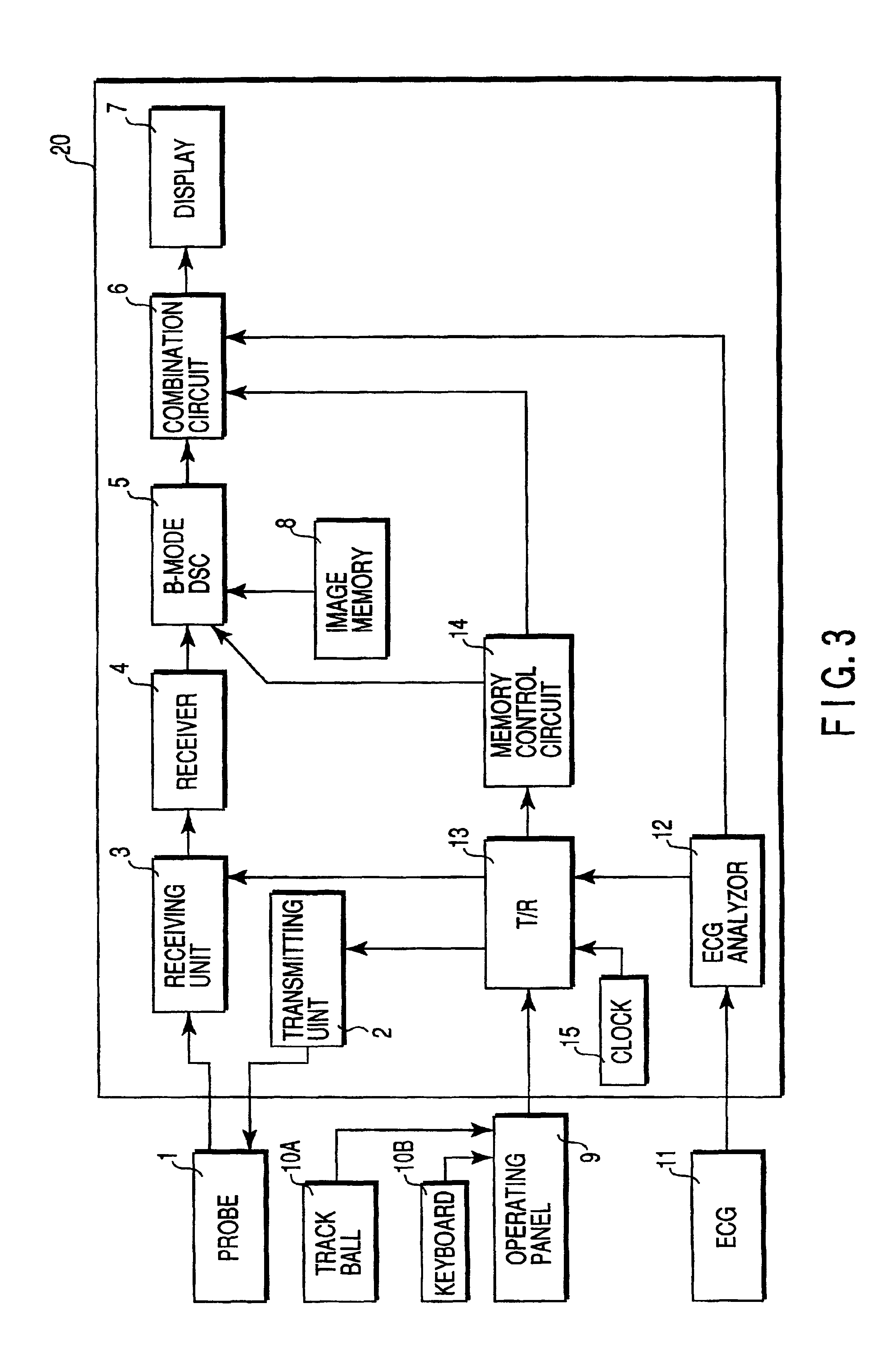
[0047]FIG. 3 shows the arrangement of an ultrasound diagnostic apparatus according to the first embodiment. An ultrasound probe 1 is connected to an apparatus body 20. The apparatus body 20 scans the inside of an object to be examined by using an ultrasound beam through the ultrasound probe 1, creates tomographic image data by processing the obtained reception signal, and displays the image. An operating panel 9 having a trackball 10A, keyboard 10B, and the like is connected to the apparatus body 20. Various operator instructions such as an instruction to set a region of interest (ROI) are input to the apparatus body 20 through the operating panel 9.

[0048]A plurality of electroacoustic conversion elements (transducers) are arrayed on the distal end portion of the ultrasound probe 1. One or a few adjacent transducers constitute one channel. RF voltage pulses are applied from a transmitting unit 2 of the apparatus body 20 to the trans...

second embodiment

(Second Embodiment)

[0085]The second embodiment provides a partial imaging method. The partial imaging method is a method of segmenting a scan plane into a plurality of local portions and scanning each local portion in an optimal scan operation sequence, instead of sequentially moving over scanning lines within the scan plane, thereby obtaining optimal (maximum) contrast on the entire scan plane and combining the resultant data into a one frame.

(Arrangement and Flow of Signals)

[0086]FIG. 9 is a block diagram showing an ultrasound diagnosis apparatus of this embodiment. The same reference numerals as in the first embodiment denote the same parts in the first embodiment, and a detailed description thereof will be omitted. A template memory 21 stores pieces of information about a plurality of models for segmenting a scan slice into a plurality of local regions (partial regions). One optimal pattern for a sliceal shape of a portion to be diagnosed is read out from the template memory 21 ...

third embodiment

(Third Embodiment)

[0106]FIG. 18 shows the arrangement of the third embodiment. A transmission / reception control circuit 13 controls the timing of pulses from a transmitting unit. This embodiment performs intermittent transmission using a timing signal from an ECG analyzer 12 or clock 15 in accordance with a mode switching instruction sent from an operating panel 9. Intermittent transmission is transmission in which frame generation intervals are sufficiently larger than those in normal continuous transmission (20 to 100 frames / sec). For example, time intervals corresponding to four or five heartbeats are input.

[0107]The transmission / reception control circuit 13 instructs a transmitting unit 2 to perform transmission of a plurality of frames per trigger (in other words, continuous scanning in a short period of time). FIG. 19 shows a conceptual rendering of this transmission. Referring to FIG. 19, five frames are continuously transmitted / received at predetermined time intervals (suffi...


PUM


Abstract

An ultrasound diagnostic apparatus for obtaining an ultrasound image of a subject into which an ultrasound contrast agent mainly composed of microbubbles is injected, comprising a probe configured to transmit / receive an ultrasound wave to / from the subject, a transmission circuit configured to drive the probe to transmit an ultrasound wave while sequentially changing a direction of an ultrasound transmission line, a reception circuit configured to generate reception line data of the number of parallel reception from ultrasound echo signals obtained by one ultrasound wave transmission, a transmission / reception control circuit configured to control the transmission and reception circuits to change the number of parallel reception during a scan sequence for generating a 1-frame ultrasound image, and an image processing unit configured to generate an ultrasound image on the basis of the reception line data.

Description

CROSS-REFERENCE TO RELATED APPLICATIONS[0001]This application is based upon and claims the benefit of priority from the prior Japanese Patent Application No. 11-309381, filed Oct. 29, 1999, the entire contents of which are incorporated herein by reference.BACKGROUND OF THE INVENTION[0002]The present invention relates to an ultrasound diagnostic apparatus suited for a contrast echo method using an ultrasound contrast agent mainly composed of microbubbles.[0003]An ultrasound image diagnostic apparatus has many advantages which other modalities, e.g., an X-ray diagnostic apparatus, X-ray computer tomography apparatus (CT scanner), magnetic resonance imaging apparatus (MRI), and nuclear medicine diagnostic apparatus (gamma camera, SPECT, and PET), do not have. For example, the ultrasound image diagnostic apparatus can generate and display images almost in real time concurrently with scanning. This apparatus is compact and inexpensive. In using the apparatus, there is no chance of exposu...

Claims


Application Information

Patent Timeline
Patent Type & Authority Patents(United States)
IPC IPC(8): A61B8/02A61B8/08A61B8/00A61B8/06
CPCG01S7/52071G01S7/52085G01S7/52087G01S7/52095G01S15/8906A61B8/481A61B8/543A61B5/0402A61B8/0883A61B5/318G06T2219/028
Inventor KAMIYAMA, NAOHISA
Owner KK TOSHIBA
Why Eureka
Try Eureka