

Apparatus for macromolecule purification
- Summary
- Abstract
- Description
- Claims
- Application Information
AI Technical Summary
Benefits of technology
Problems solved by technology
Method used
Image

Examples
Embodiment Construction
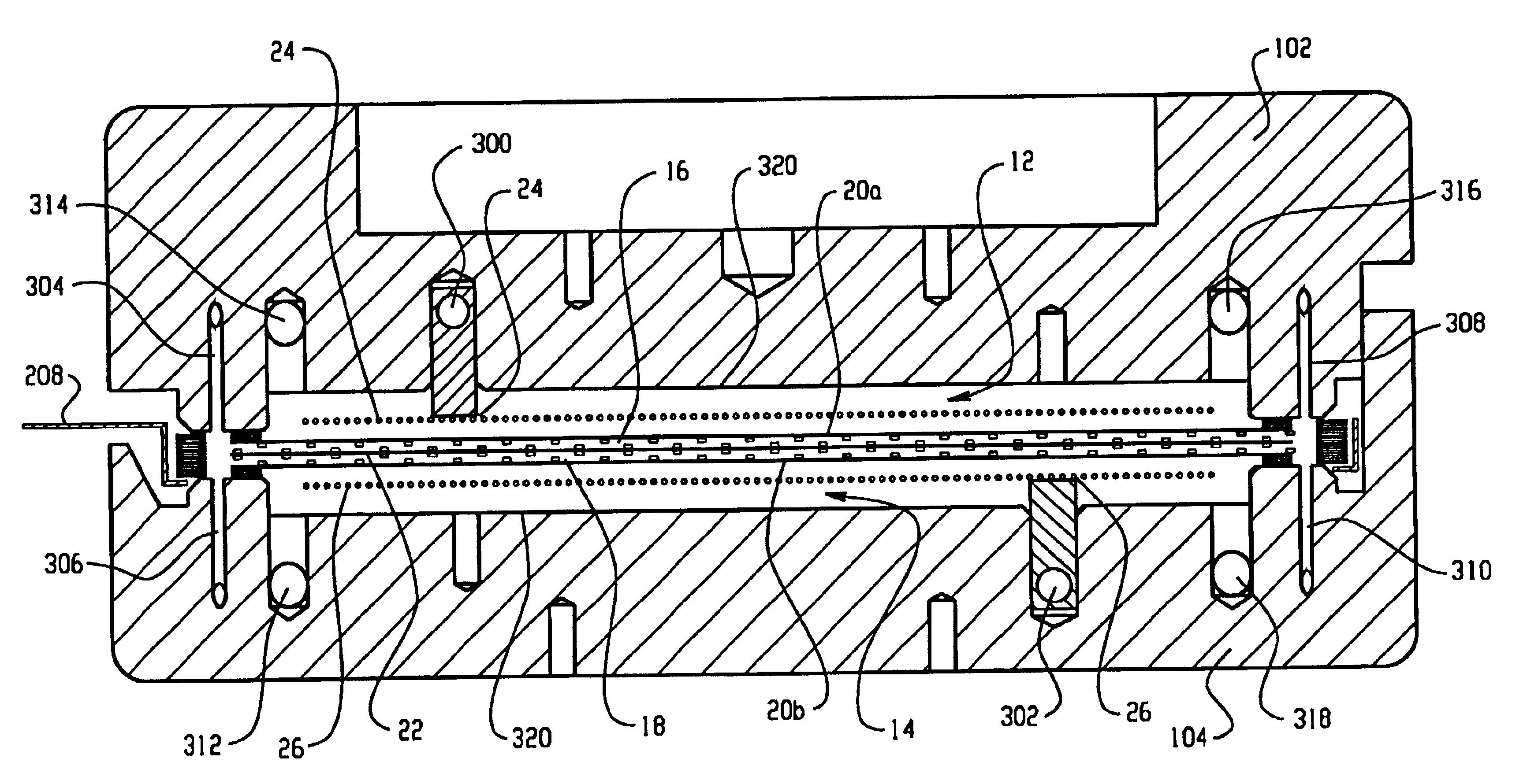
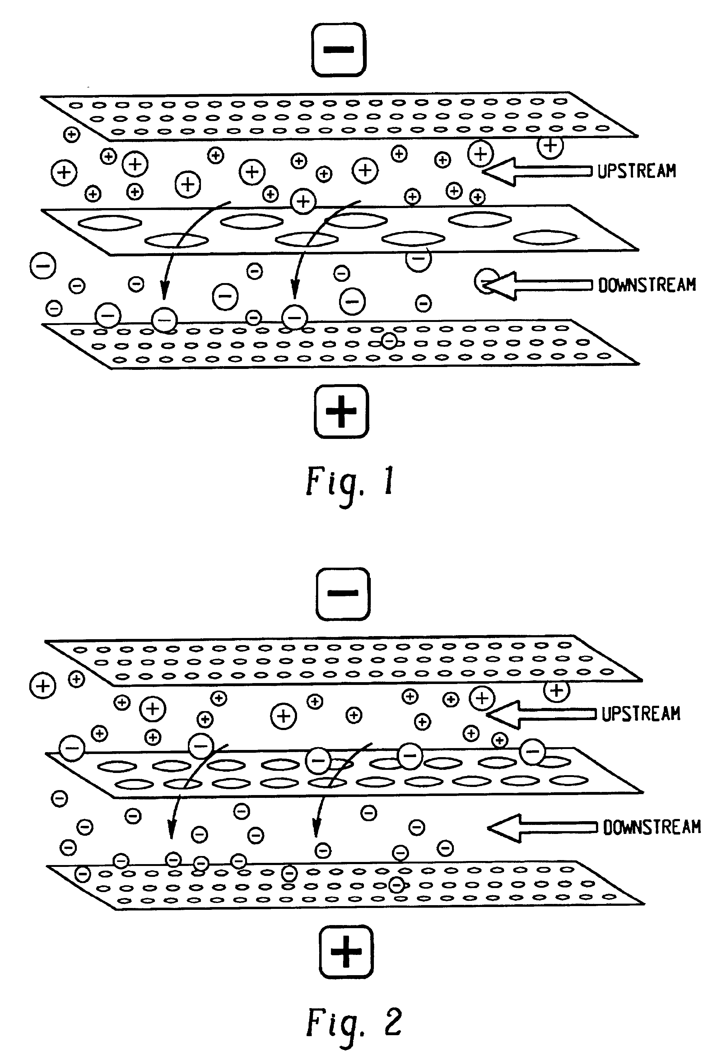
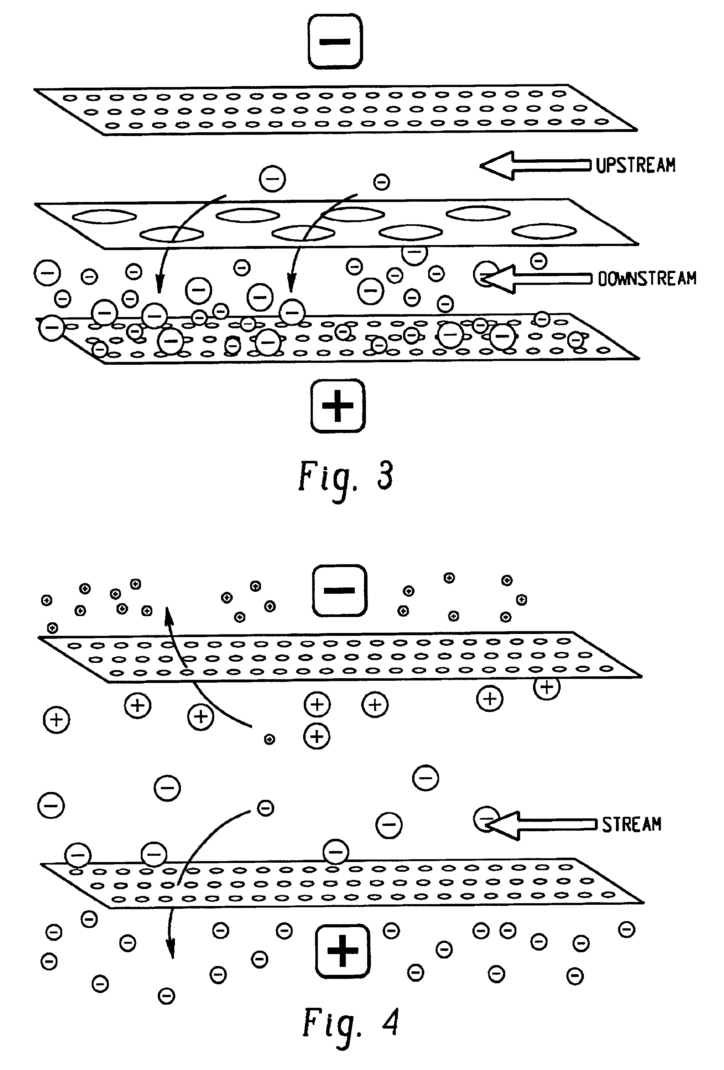
[0048]Before describing a preferred embodiment in detail, some of the principals of operation of an apparatus in accordance with the present invention will first be described. The description is not intended to limit the present invention to any one particular principal or theory of operation.
[0049]An electric field applied to macromolecules, such as proteins, in solution, will tend to cause the proteins to move to the electrodes. If the protein has a positive charge, it will tend to move to the negative electrode (cathode). Conversely, a negatively charged protein will tend to move to the positive electrode (anode).
[0050]In an apparatus in accordance with the present invention, a separation membrane may be placed in the electric field and molecules may be selectively transported between two circulating streams which may be called the upstream and the downstream. The particular separation membrane used may vary for different applications and may generally have a relatively large, bu...
PUM
| Property | Measurement | Unit |
|---|---|---|
| Lattice constant | aaaaa | aaaaa |
| Electrical conductivity | aaaaa | aaaaa |
| Shape | aaaaa | aaaaa |
Abstract
Description
Claims
Application Information