

Device for operating a high-pressure discharge lamp
a high-pressure discharge and lamp technology, applied in the direction of electric variable regulation, process and machine control, instruments, etc., can solve the problem of over-exceeding the maximum voltage rating of one of the bridge capacitors, damage to the capacitors and/or malfunction of the ballast circuit, and higher levels of the midpoint voltage of the half bridge. the effect of reducing or increasing the value of the duty cycle of the ballas
- Summary
- Abstract
- Description
- Claims
- Application Information
AI Technical Summary
Benefits of technology
Problems solved by technology
Method used
Image

Examples
Embodiment Construction
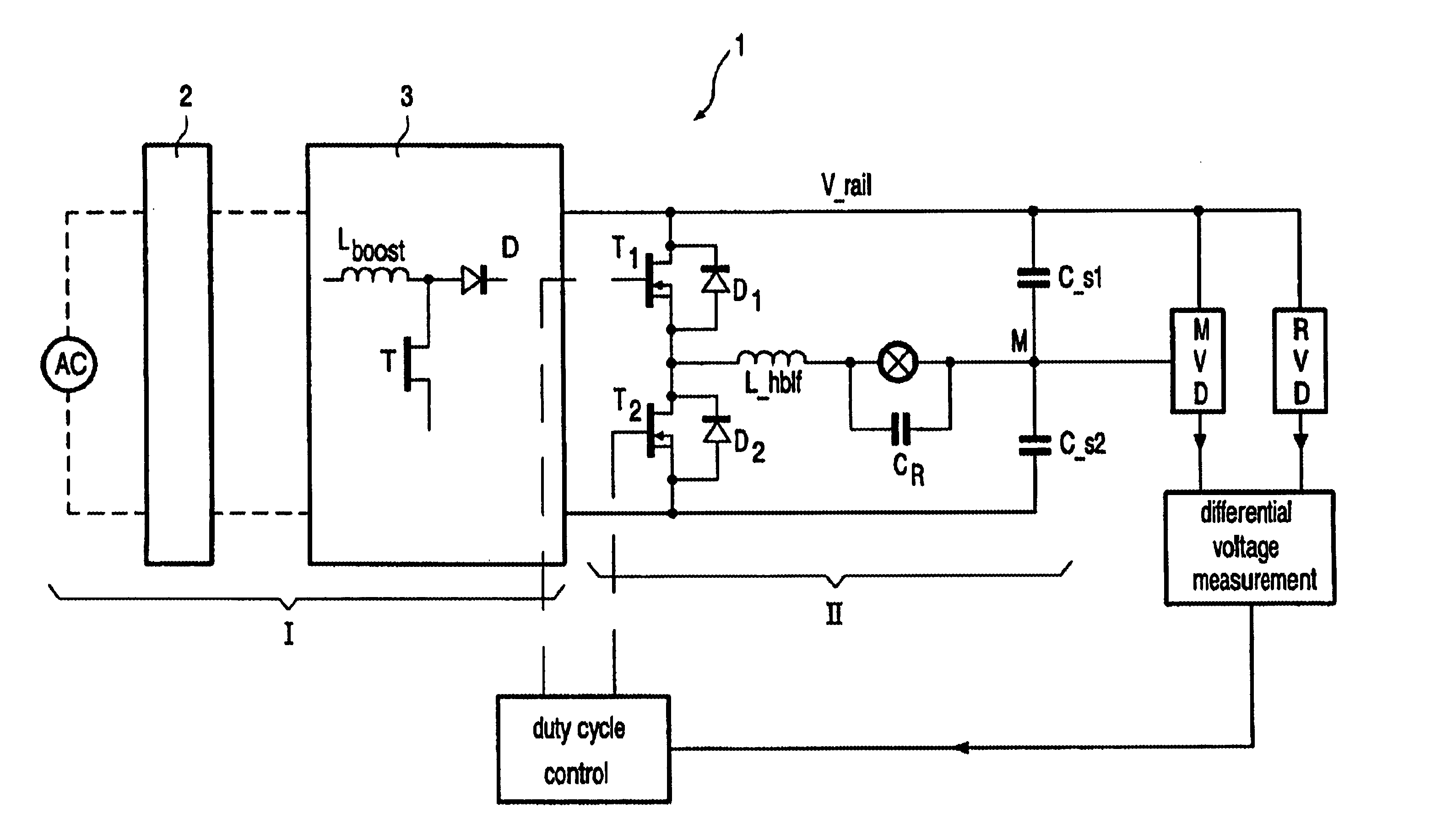
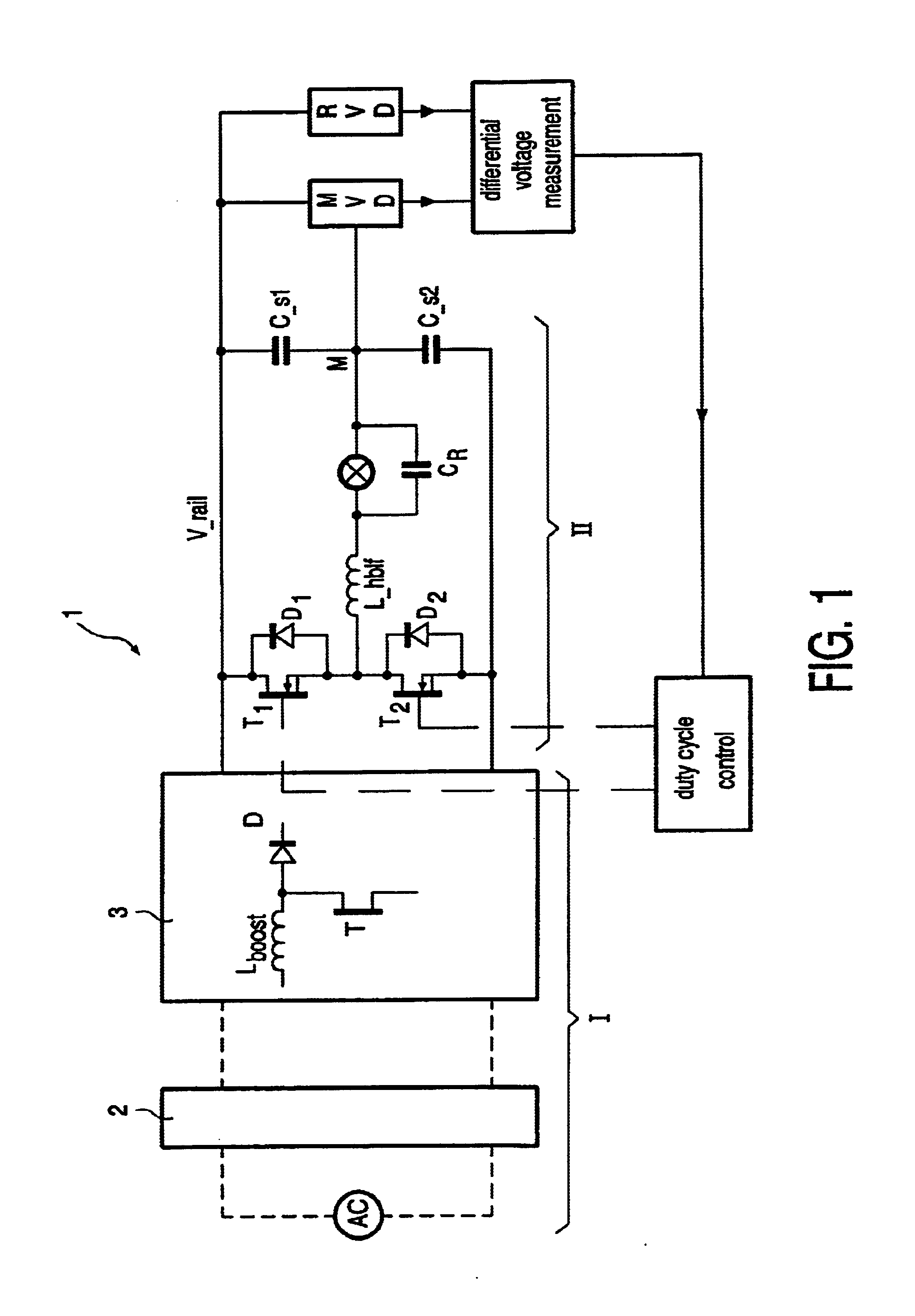
[0022]FIG. 1 shows a two-stage ballast for a high discharge lamp LA. The first stage I of the ballast comprises a rectifier 2 for converting the AC supply voltage (typically a 230 V 50 Hz mains) to a DC supply voltage and an up-converter or boost-converter 3 for boosting the DC supply voltage. In FIG. 1 a typical topology of a boost-converter or up-converter is shown. The boost-converter inter alia is composed of an inductor Lboost, a switching element T and a diode D.
[0023]During the starting phase of the lamp the output voltage or rail voltage of the switched-mode power supply SMPS is boosted to create a sufficient open circuit voltage (OCV). The open circuit voltage required in this phase of lamp operation depends on the type of HID lamp used. Typically the rail voltage is boosted during the starting phase to about 500 V to create an OCV of 250 V. During subsequent normal operation of the lamp, the rail voltage is reduced (typically to about 400 V) to increase the efficiency of t...
PUM
 Abstract
Description
Claims
Application Information