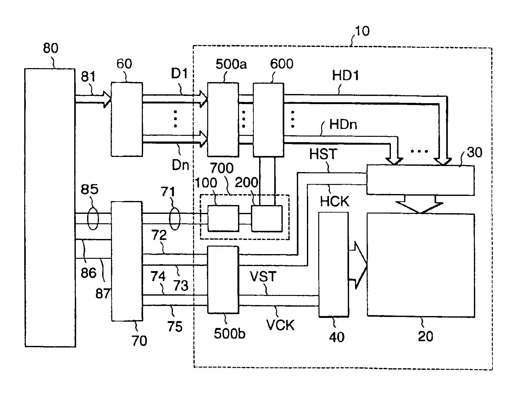
Liquid crystal display apparatus having level conversion circuit
a technology of level conversion circuit and liquid crystal display, which is applied in the direction of box making operation, instrumentation, pulse technique, etc., can solve the problem that the equivalent load capacity increase becomes an obstacle to achieve high speed operation, and achieve the effect of reducing the size of the transistor and high speed
- Summary
- Abstract
- Description
- Claims
- Application Information
AI Technical Summary
Benefits of technology
Problems solved by technology
Method used
Image
Examples
first embodiment
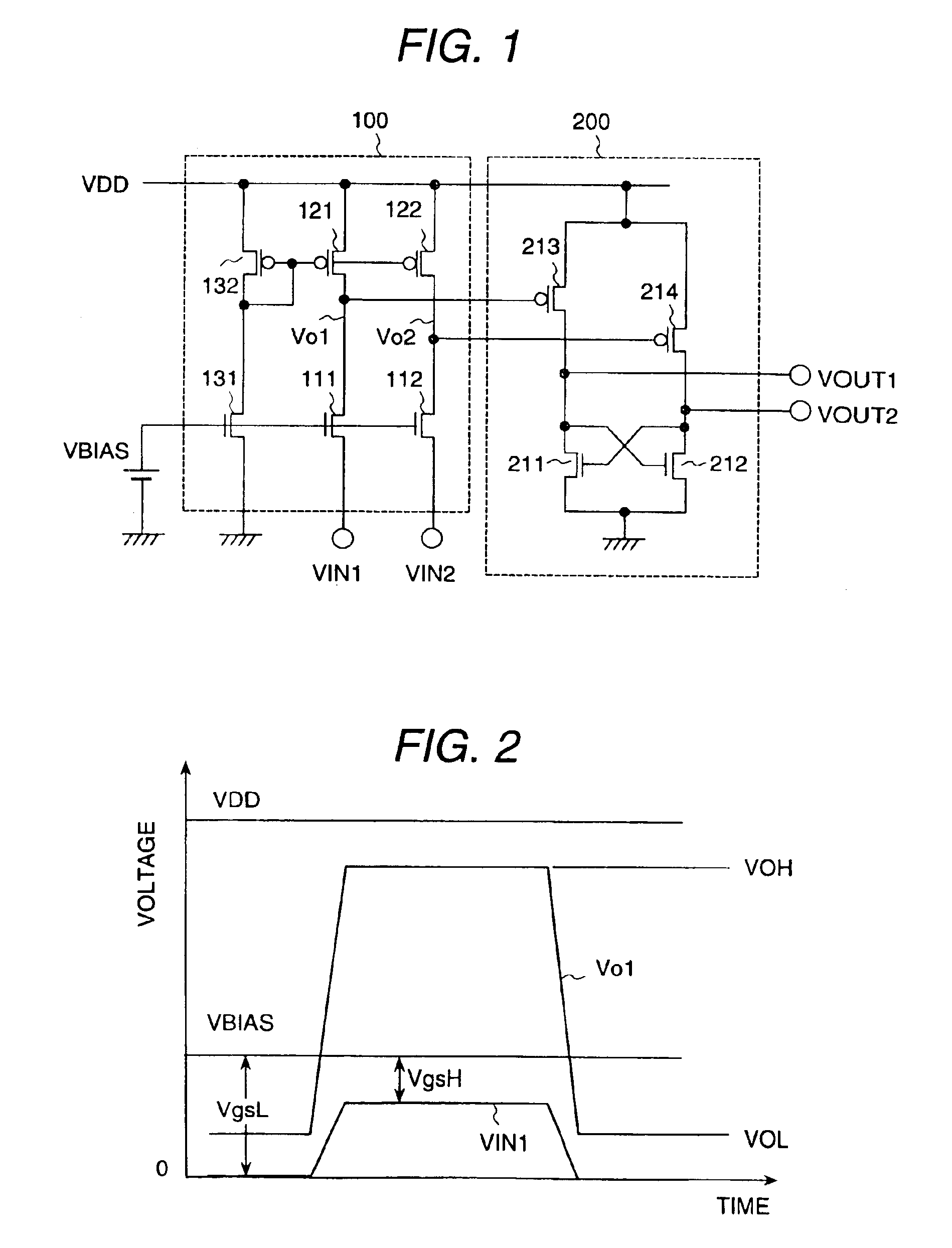
[0039]FIG. 1 shows a level conversion circuit in a liquid crystal display apparatus forming a first embodiment according to the present invention. The level conversion circuit is constituted by a level conversion unit 100 and a wave-form shaping unit 200.
[0040]The level conversion unit 100 is constituted by input transistors 111 and 112, load transistors 121 and 122, and bias transistors 131 and 132. In the level conversion unit 100, a respective gate electrode of the respective input transistors 111 and 112 is connected to a bias power supply VBIAS, a respective source electrode of the respective input transistors 111 and 112 is connected to input terminals VIN1 and VIN2, and a respective drain electrode of the respective input transistors 111 and 112 is connected to outputs Vo1 and Vo2, respectively.
[0041]In the level conversion unit 100, the gate electrodes of the respective load transistors 121 and 122 are connected in common to the bias use transistor 132, the source electrodes...
second embodiment
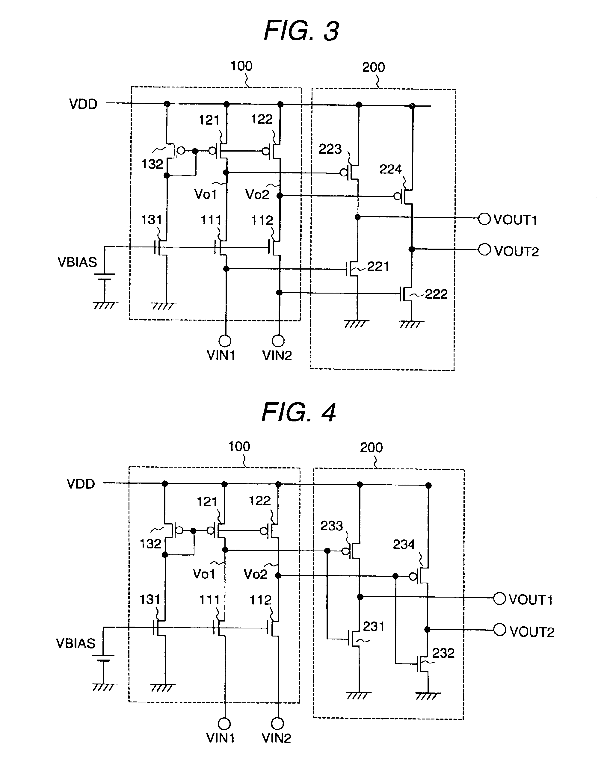
[0057]FIG. 3 shows a level conversion circuit in a liquid crystal display apparatus representing a second embodiment according to the present invention. This second embodiment according to the present invention differs from the first embodiment shown in FIG. 1, and the difference is in the wave-form shaping unit 200 shown in FIG. 3.
[0058]The wave-form shaping unit 200 of this second embodiment according to the present invention is constituted of N-type load transistors 221 and 222 and P-type input transistors 223 and 224. The respective source electrodes of the N-type load transistors 221 and 222 are grounded, the respective gate electrodes of the load transistors 221 and 222 are connected to the input terminals VIN1 and VIN2, and the respective drain electrodes of the load transistors 221 and 222 are connected to the respective drain electrodes of the P-type input transistors 223 and 224, respectively.
[0059]The respective source electrodes of the P-type input transistors 223 and 22...
third embodiment
[0064]FIG. 4 shows a level conversion circuit in a liquid crystal display apparatus representing a third embodiment according to the present invention. This third embodiment differs from the first embodiment shown in FIG. 1, and the difference is in the wave-form shaping unit 200.
[0065]The wave-form shaping unit 200 of this third embodiment according to the present invention is constituted of N-type load transistors 231 and 232 and P-type input transistors 233 and 234. Each of the N-type load transistor 231 and the P-type input transistor 233 and each of the N-type load transistor 232 and the P-type input transistor 234 constitutes, respectively, an inverter circuit.
[0066]The operation of the wave-form shaping unit 200 constituted as described above will be explained. As one example of the conditions of operation, the voltages of the input terminals VIN1 and VIN2 are respectively 3.3 V and 0 V, the voltage of the power supply VDD is 15 V and the voltage of the bias power supply is 5...
PUM
 Abstract
Description
Claims
Application Information
 - R&D
- Intellectual Property
- Life Sciences
- Materials
- Tech Scout
- Unparalleled Data Quality
- Higher Quality Content
- 60% Fewer Hallucinations
Browse by: Latest US Patents, China's latest patents, Technical Efficacy Thesaurus, Application Domain, Technology Topic, Popular Technical Reports.
© 2025 PatSnap. All rights reserved.Legal|Privacy policy|Modern Slavery Act Transparency Statement|Sitemap|About US| Contact US: help@patsnap.com


