Vehicle air conditioner with vapor-compression refrigerant cycle

Active Publication Date: 2005-07-26
DENSO CORP
View PDF15 Cites 28 Cited by
  • Summary
  • Abstract
  • Description
  • Claims
  • Application Information

AI Technical Summary

Benefits of technology

[0007]In view of the above-mentioned problem, it is an object of the present invention to provide a vehicle air conditioner with a refrigerant cycle. It is another object of the present invention to provide a vehicle air conditioner that eliminates a fog immediately even if a windshield of the vehicle is fogged.
[0009]Accordingly, when the air to be blown into the compartment is dehumidified and heated, the interior heat exchanger dehumidifies and cools the air passing through the interior heat exchanger, and then, the air having been dehumidified and cooled in the interior heat exchanger is directly or indirectly heated using the heating source from the high-temperature refrigerant of the refrigerant cycle. As a result, low-humidity and high-temperature air is supplied into the compartment. Therefore, when the air conditioner is used for a vehicle, it can prevent the window glass such as the windshield of the vehicle from being fogged, and eliminate a fog immediately by blowing the low-humidity and high-temperature air even if the windshield of the vehicle is fogged, because the low-humidity and high-temperature air is supplied into the passenger compartment eliminates the fog. Further, the vehicle air conditioner can heat the compartment immediately, by the high-temperature refrigerant discharged from the compressor even when engine-cooling water for cooling a vehicle engine is at a low temperature such as in a case just after starting engine.
[0010]Preferably, the decompression unit includes an ejector. The ejector decompresses refrigerant discharged from the compressor while sucking gas refrigerant from the interior heat exchanger, and converts expansion energy to pressure energy to increase pressure of refrigerant to be sucked to the compressor. When refrigerant is evaporated in the interior heat exchanger to cool air passing through the interior heat exchanger, refrigerant is decompressed in the ejector. In this case, the ejector decompresses the refrigerant effectively, so that cooling performance of the air conditioner can be improved.
[0011]Preferably, the air conditioner includes an air conditioning case for defining an air passage through which air flows into the compartment. The air conditioning case is disposed to accommodate the interior heat exchanger. More preferably, the heater includes a heater core and a fluid-refrigerant heat exchanger. The heater core is disposed in the air conditioning case downstream from the interior heat exchanger in an air flow direction for heating air passing therethrough by using a fluid flowing therein as a heating source. The fluid-refrigerant heat exchanger is disposed outside the air conditioning case for heating the fluid circulating in the heater core by using the high-temperature refrigerant discharged from the compressor as a heating source. In this case, the air to be blown into the compartment is heated in the heater core using the heating source from the high temperature refrigerant in the dehumidifying and cooling operation. Therefore, the vehicle air conditioner can heat the compartment immediately by using the high-temperature refrigerant discharged from the compressor even when the fluid flowing into the heater core is at a low temperature.
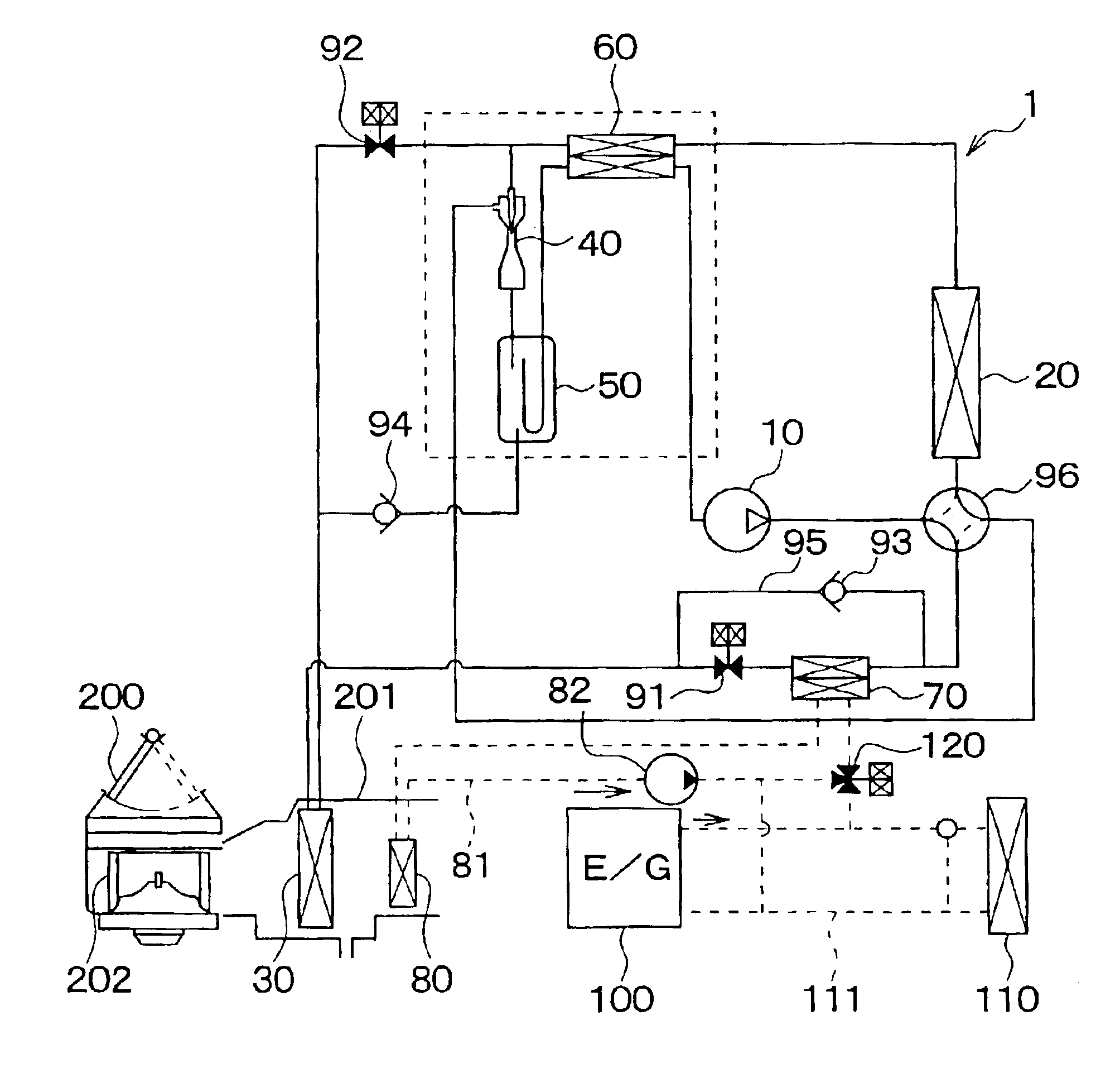
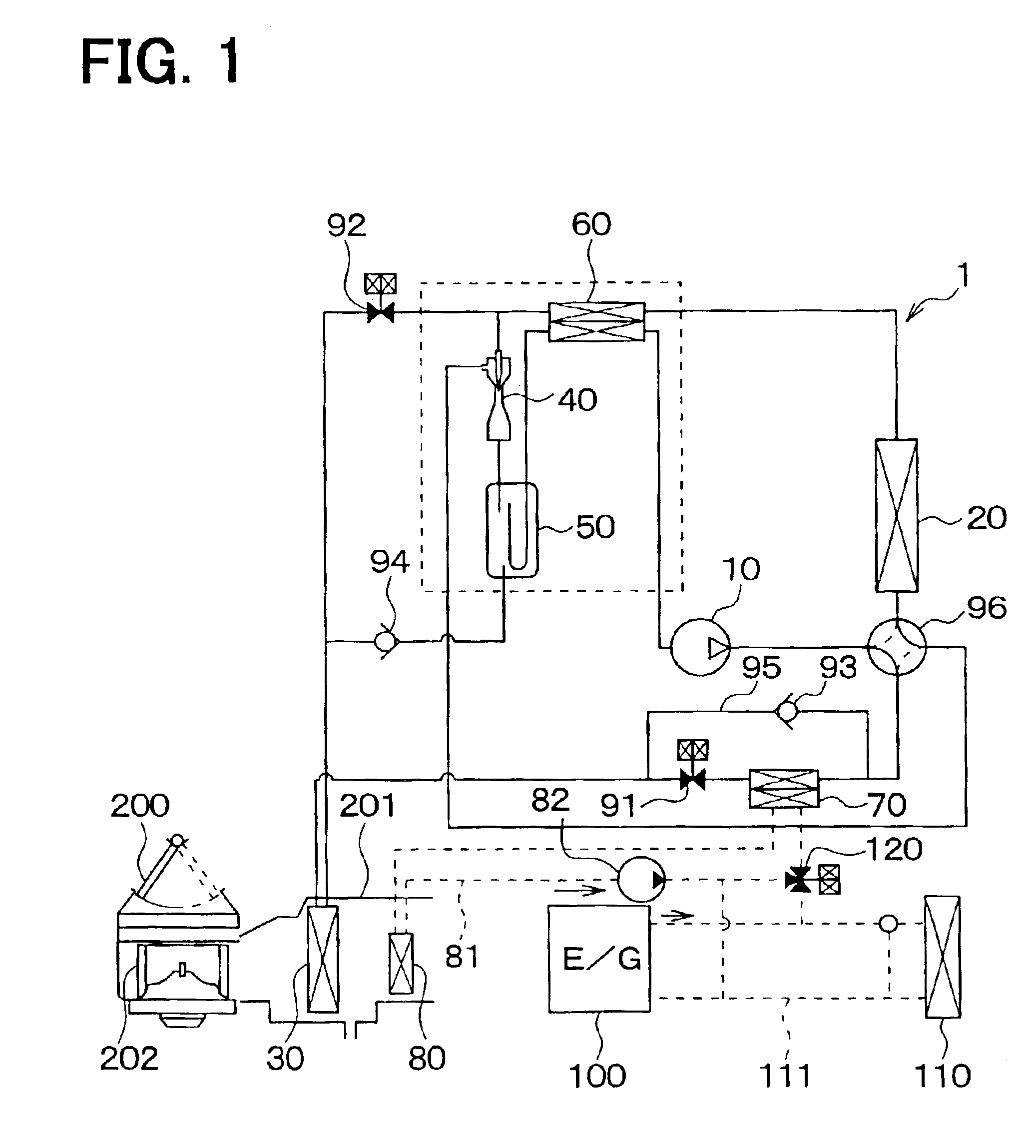
[0012]Further, the refrigerant cycle includes a gas-liquid separator for separating refrigerant into gas refrigerant and liquid refrigerant and a switching unit. The switching unit changes a refrigerant flow to switch one of at least a first operation where refrigerant is evaporated in the interior heat exchanger while the high-temperature refrigerant bypasses the fluid-refrigerant heat exchanger, and a second operation where refrigerant is evaporated in the interior heat exchanger while the high-temperature refrigerant flows through the fluid-refrigerant heat exchanger to heat the fluid. In each of the first operation and the second operation, the ejector decompresses refrigerant discharged from the compressor while sucking gas refrigerant evaporated in the interior heat exchanger. In the first operation, refrigerant discharged from the compressor circulates the exterior heat exchanger, the ejector, the gas-liquid separator and the compressor in this order, while refrigerant in the gas-liquid separator flows through the interior heat exchanger, the ejector and the gas-liquid separator in this order. In the second operation, refrigerant discharged from the compressor circulates the fluid-refrigerant heat exchanger, the exterior heat exchanger, the ejector, the gas-liquid separator and the compressor in this order, while refrigerant in the gas-liquid separator flows through the interior heat exchanger, the ejector and the gas-liquid separator in this order. Therefore, when the second operation is performed, the compartment can be effectively dehumidified and heated.
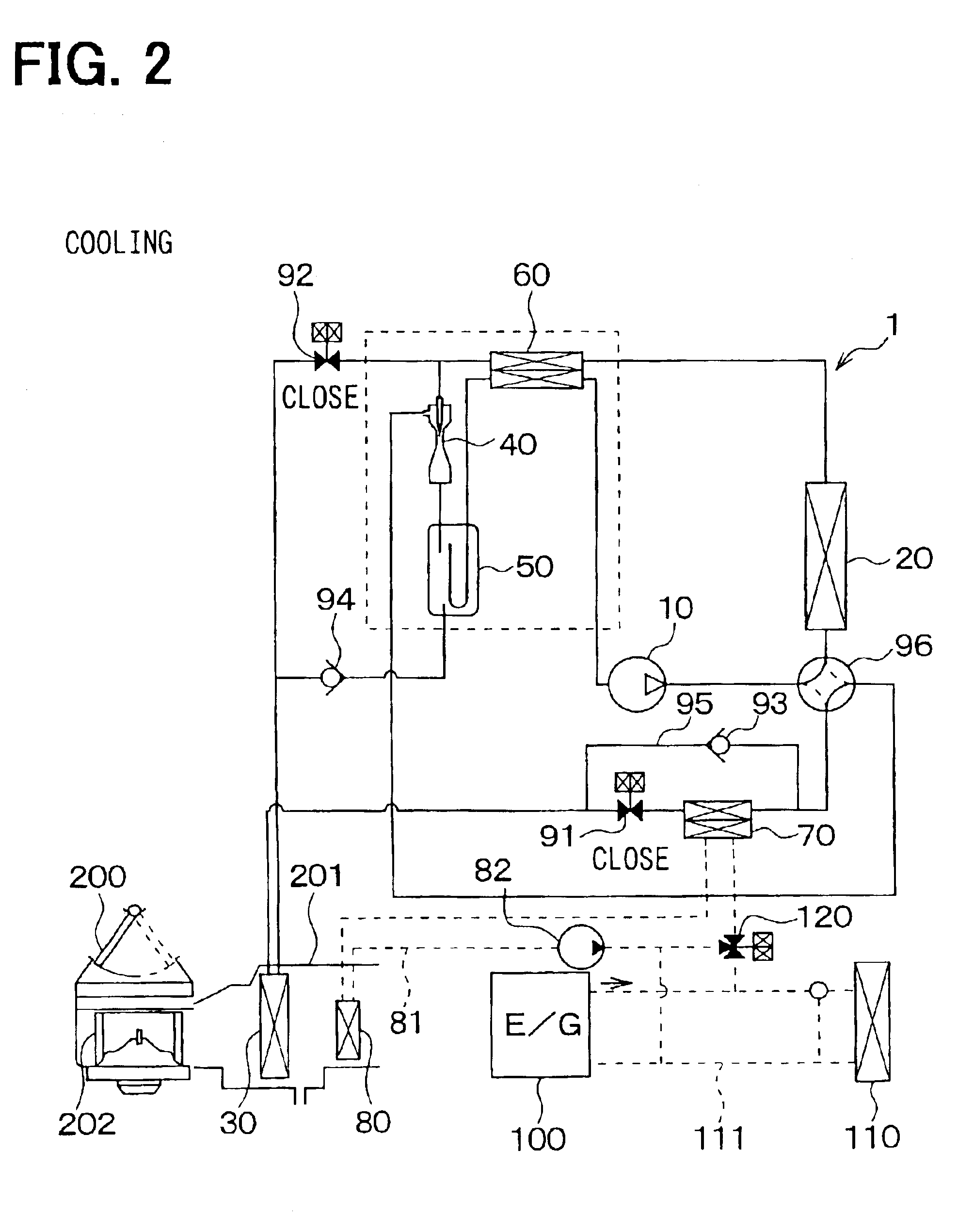
[0014]When the dehumidifying unit further includes first and second throttles, a switching unit switches one of a cooling operation where the compartment is cooled, a dehumidifying and heating operation where the compartment is dehumidified while being heated, and a heating operation where the compartment is heated. In the cooling operation, refrigerant after being decompressed is evaporated in the interior heat exchanger to cool air passing therethrough, and high-pressure refrigerant discharged from the compressor is decompressed in the ejector while sucking gas refrigerant from the interior heat exchanger. In the dehumidifying and heating operation, refrigerant after being decompressed is evaporated in the interior heat exchanger to cool and dehumidify air passing therethrough, and high-pressure refrigerant discharged from the compressor is decompressed by the first throttle. Accordingly, the dehumidifying and heating operation can be effectively performed. Further, in the third operation, high-temperature refrigerant before being decompressed flows into the interior heat exchanger to heat air passing therethrough, and the high-pressure refrigerant is decompressed in the second throttle. Even in this air conditioner, the heater can be used to directly heat air or can be used to indirectly heat air.

Problems solved by technology

Therefore, a windshield of an automotive vehicle is readily fogged.

Method used


Image

  • Vehicle air conditioner with vapor-compression refrigerant cycle
  • Vehicle air conditioner with vapor-compression refrigerant cycle
  • Vehicle air conditioner with vapor-compression refrigerant cycle

Examples


first embodiment

[0030](First Embodiment)

[0031]In the first embodiment, an air conditioner of the present invention is typically used for a vehicle. As shown in FIG. 1, the air conditioner includes a vapor-compression refrigerant cycle 1 having an ejector type decompression device. The refrigerant cycle 1 includes a compressor 10, an exterior heat exchanger 20, an interior heat exchanger 30, an ejector 40, a gas-liquid separator 50, an inner heat exchanger 60, a water-refrigerant heat exchanger 70, and a heater core 80.

[0032]The compressor 10 is a variable displacement compressor operated by a driving force from a driving engine, and is used as a pumping means for sucking and compressing refrigerant. The compressor 10 variably controls a displacement so as to absorb a variation of an engine speed and an air conditioning load. Here, the displacement means a theoretical displacement discharged from a discharge port of the compressor 10 by one rotation cycle of a shaft in the compressor 10.

[0033]In thi...

second embodiment

[0066](Second Embodiment)

[0067]The second embodiment is a modification of the first embodiment. Specifically, as shown in FIG. 5, the water-refrigerant heat exchanger 70 is disposed upstream from the switching valve 96 in the refrigerant flowing direction. In other words, the water-refrigerant heat exchanger 70 is disposed on the discharge side of the compressor 10 rather than the switching valve 96.

[0068]Although a refrigerant system of the second embodiment is modified, operation of the refrigerant system of the second embodiment is similar to that of the above-described first embodiment, and the advantage similar to the first embodiment can be obtained.

third embodiment

[0069](Third Embodiment)

[0070]In the dehumidifying and heating operation of the above-described first embodiment, the water-refrigerant heat exchanger 70 heats the engine-cooling water circulating through the heater core 80, so that the air to be blown into the compartment is heated indirectly by the high-temperature refrigerant as a heating source discharged from the compressor 10. In the third embodiment, as shown in FIG. 6, the interior heat exchanger 30 is used as a first interior heat exchanger, and a second interior heat exchanger 31 is disposed downstream from the interior heat exchanger 30 in the air flowing direction. The high-temperature refrigerant discharged from the compressor 10 is introduced in the second interior heat exchanger 31 so that the air to be blown into the compartment is heated directly by the second interior heat exchanger 31.

[0071]Next, characteristic operation and its effect of the air conditioner in this embodiment will be now described.

[0072]1. Coolin...


PUM


Abstract

An air conditioner includes a compressor for compressing refrigerant, an exterior heat exchanger for performing heat exchange between refrigerant and outside air, an interior heat exchanger for performing heat exchange between the refrigerant and air to be blown into the compartment, a decompression unit for decompressing high-pressure refrigerant, and a heater that heats air using high-temperature refrigerant discharged from the compressor as a heating source. In a dehumidifying and heating operation, refrigerant in the interior heat exchanger absorbs heat from air so that the air is cooled and dehumidified, and the heater heats air having been dehumidified and cooled by using the heating source, so that low-humidity and high-temperature air is supplied into the compartment. The heater can be disposed to indirectly heat air by heating a fluid flowing through a heater core for heating air, or to directly heat air to be blown into the compartment.

Description

CROSS REFERENCE TO RELATED APPLICATION[0001]This application is based on Japanese Patent Application No. 2002-126404 filed on Apr. 26, 2002, the disclosure of which is incorporated herein by reference.BACKGROUND OF THE INVENTION[0002]1. Field of the Invention[0003]The present invention relates to an air conditioner with a vapor-compression refrigerant cycle. The air conditioner is suitably used for a vehicle.[0004]2. Related Art[0005]A vehicle air conditioner in a prior art switches a cooling operation and a heating operation, by switching an operation for flowing high-pressure refrigerant in an interior heat exchanger and an operation for flowing low-pressure refrigerant in the interior heat exchanger.[0006]However, in this vehicle air conditioner, when the cooling operation is set for dehumidifying a passenger compartment, condensed water is generated on a surface of the interior heat exchanger. After that, when the heating operation is set, the condensed water remained on the sur...

Claims


Application Information

Patent Timeline
IPC IPC(8): B60H1/04B60H1/00B60H1/08F25B13/00F25B9/00B60H1/03B60H1/32B60H1/22F25B1/00F25B6/04
CPCB60H1/00921B60H1/08B60H2001/00928B60H2001/00935B60H2001/00949B60H2001/3298F25B9/008F25B13/00F25B2309/061F25B2313/0212F25B2313/0213F25B2313/02321F25B2313/02343F25B2313/02344F25B2327/001F25B2341/0012F25B2341/066F25B2400/0403F25B2400/0405F25B2400/0417F25B41/385F25B41/39
Inventor TAKEUCHI, HIROTSUGU
Owner DENSO CORP
Why Eureka
Try Eureka