
Oxygen monitoring apparatus and methods of using the apparatus

Inactive Publication Date: 2010-11-16
RIC INVESTMENTS LLC
View PDF21 Cites 28 Cited by
  • Summary
  • Abstract
  • Description
  • Claims
  • Application Information

AI Technical Summary

Benefits of technology

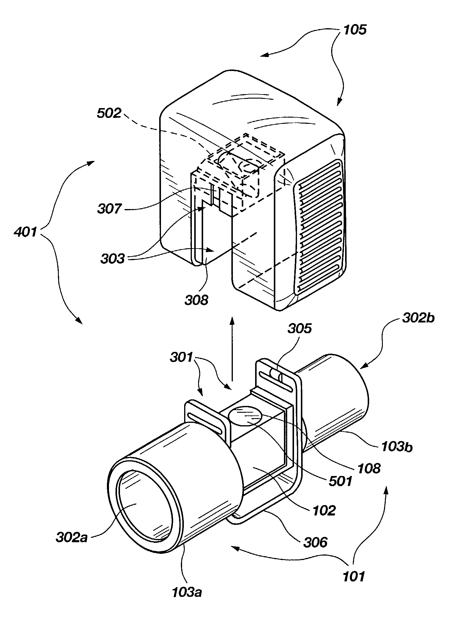
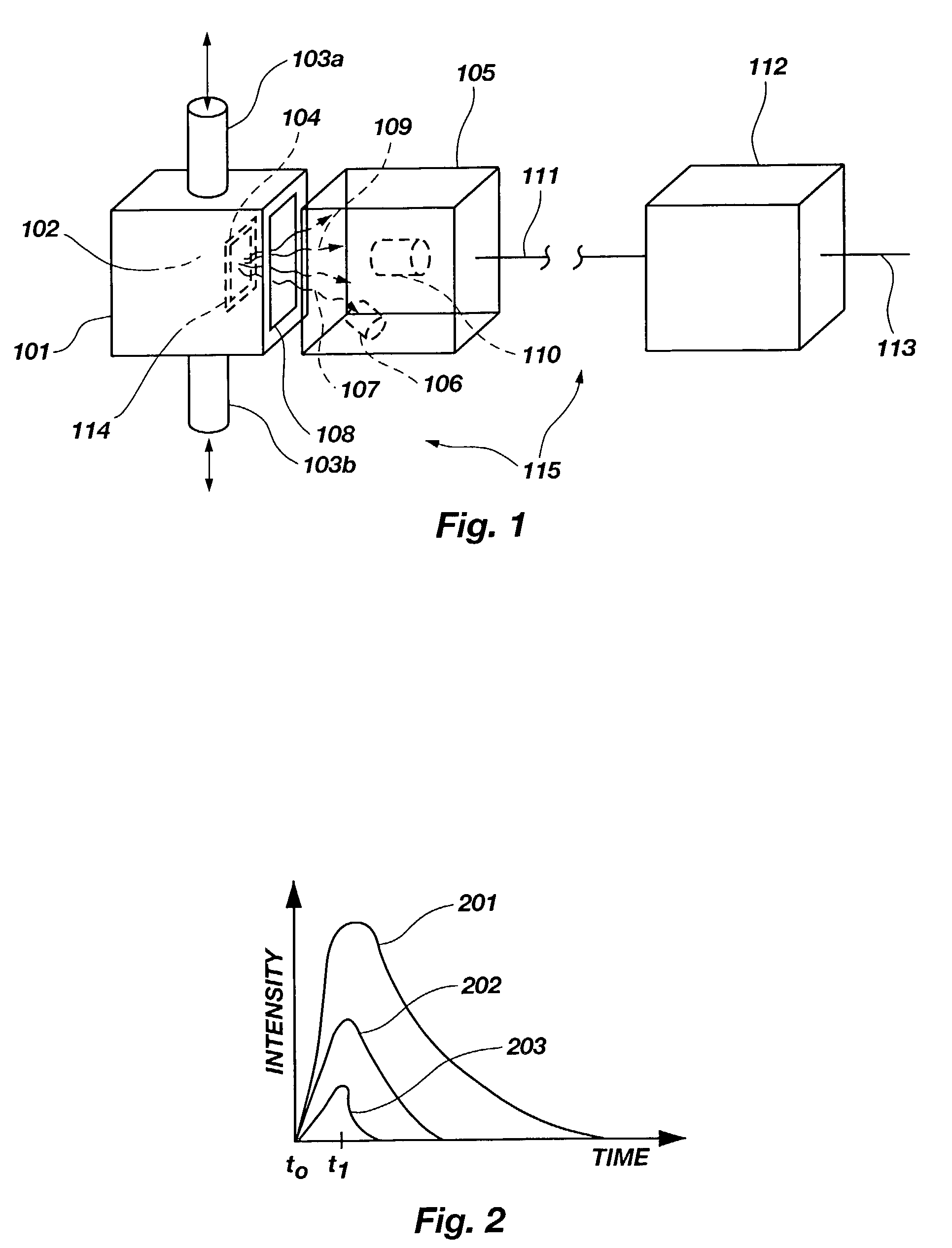
[0048]This “single-sided” arrangement of the light source, oxygen sensor, and photodetector has a number of significant advantages. Specifically, in the systems disclosed in the copending applications, intimate contact between heater element components of the transducer and the sampling device is required, and this can prove difficult to achieve. This problem is eliminated in the single-sided systems disclosed herein by supporting the sensor from a near side optical window and by heating that window which thereupon transfers thermal energy to the associated sensor.
[0049]Another important advantage of the single-sided arrangements disclosed herein is that the energy of excitation indicative of oxygen concentration does not have to traverse the gases flowing through the sampling component. Consequently, the degradation in signal attributable to interactions between the gas being sampled and the energy of excitation is eliminated, making a significantly less-degraded signal available to the photodetector.
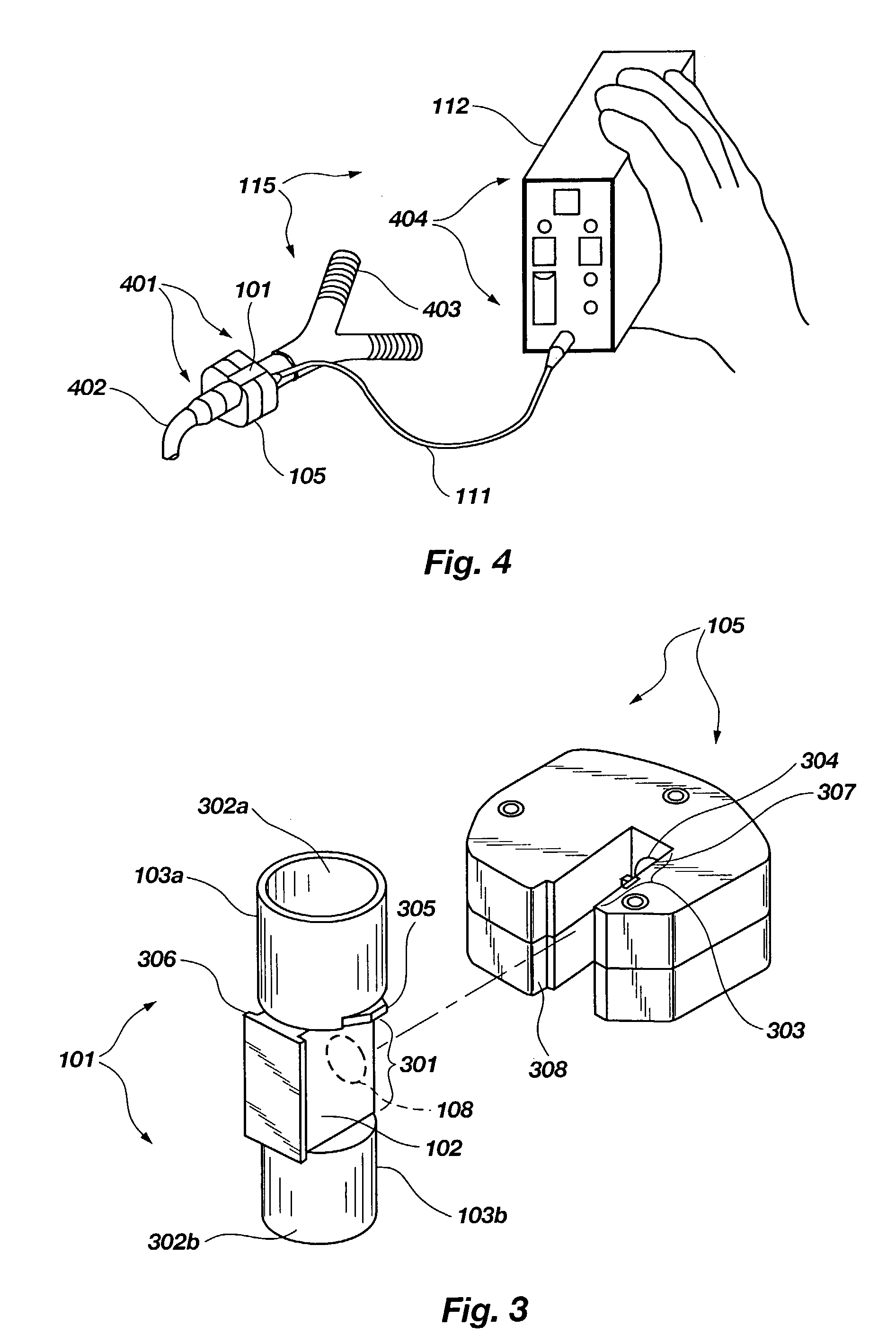
[0050]One of the two apertures present in the sampling component of the previously disclosed systems is eliminated, along with a sensor film heating component installed in that aperture. This leads directly to a less complex, less expensive sampling component. This is important because the sensor film has a finite, relatively short life, and the sampling unit must accordingly be periodically replaced. In fact, in an important application of the present invention—on-airway use in a hospital—it is highly desirable that the cost of the sampling unit be low enough to make it feasible to discard this unit after a single use.
[0053]Systems with the advantages just described differ physically from those disclosed in the copending applications in that the optical window in the airway adapter or sampling cell is employed as a mount or support for the sensor film and is also employed to transfer to the film the heat needed to keep it at a constant temperature. As will be apparent, this also results in the window being heated to a high enough temperature to eliminate fogging. Various schemes for heating the transparent window might be employed. One suitable approach is to surround the transparent window of the gas sampling device with a heater in a ring configuration. Of importance in systems employing the principles of the present invention is a secure application of the film-type sensor to the optical window of the sampling device. An adhesive layer may be employed to bond the sensor film to the window, or it may be solvent bonded to the window. Another approach is to employ a retaining ring to stretch the film over and secure it to the window. A related approach is to employ a retaining ring bounded on one side with a fine mesh to retain the film and press it against the window. The last-mentioned approach has the advantage that the film is physically retained without an adhesive and will not loosen. In addition, the mesh, with its location on the gas side of the sensor, enhances heat conduction over that side of the sensor, producing exceptional thermal stability.
[0054]In monitoring apparatus embodying the principles of the present invention, light not indicative of the concentration of oxygen in the gas being monitored is preferably kept from the detector of that apparatus by locating a blue dichroic filter and an infrared-blocking filter in line with and on the output side of the light source and by summarily locating a red dichroic filter and a red glass filter in front of the detector apparatus. Because this arrangement eliminates essentially all of the light which is not part of the signal indicative of oxygen concentration, the light collection efficiency is increased to the extent that the intensity of the exciting light from the LED or other source can be reduced. This is important because reducing the intensity of the light from the source significantly increases the service life of the sensor. This is particularly significant in sidestream applications of the present invention where the sensor is not apt to be replaced each time it is used.

Problems solved by technology

Specifically, in the systems disclosed in the copending applications, intimate contact between heater element components of the transducer and the sampling device is required, and this can prove difficult to achieve.

Method used


Image

  • Oxygen monitoring apparatus and methods of using the apparatus
  • Oxygen monitoring apparatus and methods of using the apparatus
  • Oxygen monitoring apparatus and methods of using the apparatus

Examples


Embodiment Construction

[0073]The descriptions contained herein adhere to a numbering convention intended to facilitate understanding and make for easy cross-referencing of described features between figures. In this convention, the first digit (for features indicated by a three-digit reference number) or the first two digits (for features indicated by a four-digit reference number) correspond(s) to the figure number in which the feature is first described. Like features are thus identified by the same reference number throughout the detailed description. In some instances, features described by the same reference number may have a different physical appearance in two or more figures. In this case, the use of a like reference number is especially useful in drawing the attention of the reader to various physical embodiments that a given feature of the invention may have. Features first introduced within the same figure are numbered more-or-less consecutively in a manner corresponding to the order in which t...


PUM


Abstract

Apparatus or systems which employ luminescence-quenching to produce a signal indicative of oxygen concentration. Components of such systems include: (1) an airway adapter, sampling cell, or the like having a casing and a sensor which is excited into luminescence with the luminescence decaying in a manner reflecting the concentration of oxygen in gases flowing through the airway adapter or other flow device and is in intimate contact with a window in the casing; (2) a transducer which has a light source for exciting a luminescable composition in the sensor into luminescence, a light sensitive detector for converting energy emitted from the luminescing composition as that the composition is quenched into an electrical signal indicative of oxygen concentration in the gases being monitored, and a casing which locates the light source and detector in close physical proximity to the window but on the side thereof opposite the sensor; and (3) subsystems for maintaining the sensor temperature constant and the temperature of the window above condensation temperature and for processing the signal generated by the light sensitive detector. Airway adapters, sampling cells, and transducers for such systems are also disclosed.

Description

CROSS-REFERENCE TO RELATED APPLICATION[0001]This application is a continuation of application Ser. No. 09 / 769,015, filed Jan. 24, 2001 now U.S. Pat. No. 6,632,402.BACKGROUND OF THE INVENTION[0002]1. Field of the Invention[0003]The present invention relates to the monitoring of oxygen concentration and, more particularly, to novel, improved methods and apparatus for monitoring the concentration of oxygen in respiratory and other gases.[0004]2. State of the Art[0005]The most common cause of anesthetic and ventilator related mortality and morbidity is inadequate delivery of oxygen to a patient's tissues. Therefore, the monitoring of static inspired oxygen concentration has long been a safety standard of practice to ensure detection of hypoxic gas delivery to patients undergoing surgery and to those on mechanical ventilators and receiving supplemental oxygen therapy. However, monitoring the static inspired fraction of inhaled oxygen does not always guarantee adequate oxygen delivery to ...

Claims


Application Information

Patent Timeline
IPC IPC(8): G01N21/64G01N21/75G01N33/483G01N33/497
CPCG01N21/6408G01N21/783Y10T436/209163G01N2021/7786Y10T436/207497G01N2021/6432
Inventor BLAZEWICZ, PERRY R.MACE, LESLIE E.APPERSON, JERRY R.
Owner RIC INVESTMENTS LLC
Learn More