Manually actuated pump assembly

a pump assembly and manual operation technology, applied in the field of manual operation of the pump assembly, can solve the problems of residual product drying along the escape path, seizing the piston, and the induced force of compressed air may never reach a high enough pressure to overcome the spring closing force of the second one, so as to reduce the number of strokes, hinder or interfere, and increase the compression efficiency of the pump assembly

Inactive Publication Date: 2005-07-26
KNICKERBOCKER MICHAEL G
View PDF16 Cites 16 Cited by
  • Summary
  • Abstract
  • Description
  • Claims
  • Application Information

AI Technical Summary

Benefits of technology

[0012]Still another object of the invention is to increase the compression efficiency of the pump assembly and also minimize the number of strokes required to “prime” the pump assembly by providing a spring which is not located along or in communication with the product dispensing flow path so that the spring is not hindered by...

Problems solved by technology

Product dispensing requirements are increasingly more demanding.
The compressed air also induces an opening force on the second one-way valve but, in most cases, the induced force of the compressed air may never reach a high enough pressure to overcome the spring closing force of the second one-way valve.
The first method is to allow the air to escape around the piston which can result in re...

Method used


Image

  • Manually actuated pump assembly
  • Manually actuated pump assembly
  • Manually actuated pump assembly

Examples


Embodiment Construction

[0027]While this invention is susceptible to various embodiments, the specification and the accompanying drawings disclose two specific forms as examples of the present invention. For ease of description, the pump assembly embodying this invention is described in the normal operating position, in terms such as: upper, lower, horizontal, etc., are used with reference to this position. It will be understood, however, that the pumps and components embodying this invention may be manufactured, stored, transported, used, and sold in an orientation other than the position described.

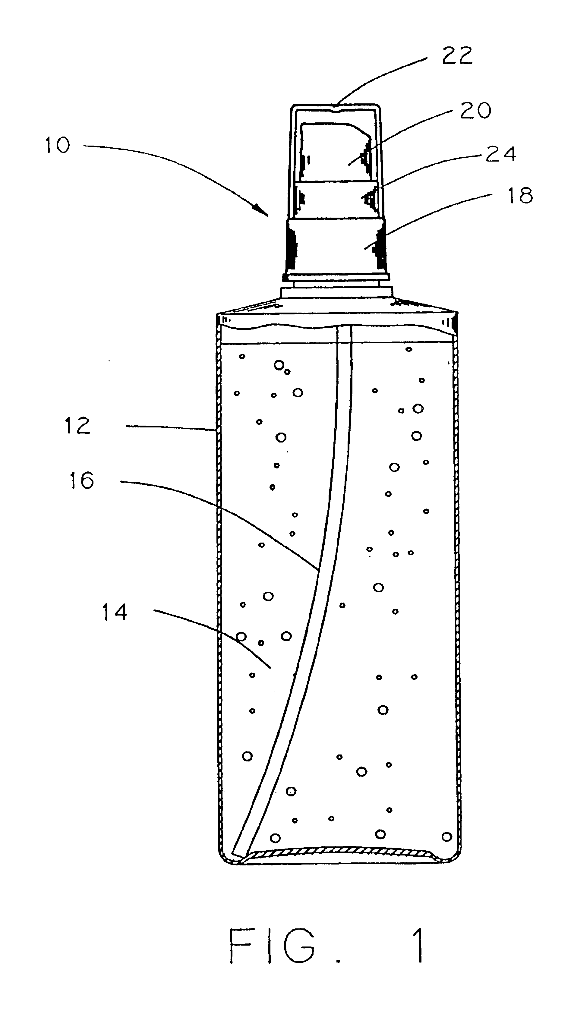
[0028]Turning first to FIG. 1, a brief description concerning the improved pump assembly 10, according to the present invention, used in combination with a prior art container 12 will now be provided. As can be seen in this Figure, the container 12 is a generally closed plastic container which has a spout (not shown in detail) formed on the top surface of the container. The spout is provided with an external th...


PUM


Abstract

A finger operated pump assembly comprising a pump body (60, 160) having a base (64, 164) supporting an outer housing (62, 162) and an inner housing (66, 166) and defining a first portion of a compression chamber (68) therebetween. A piston (82) has an annular lip and has a piston outlet defined by a poppet valve seat. A poppet (98) is accommodated by the inner housing (66, 166) and biased away from the base into engagement with the poppet valve seat by a spring (104). The poppet (98) and inner housing (66, 166) define an interior cavity (100). A peripheral passageway (74) communicates with the compression chamber (68) and includes a one-way valve (76). A ventilation port (110) is provided int the interior cavity (100) so that during operation of (98), it may operate at ambient pressure.

Description

FIELD OF THE INVENTION[0001]The invention relates to an improved manually operated pump assembly, categorized as an accumulative pump, for dispensing a product under high pressure. The pump assembly comprises a compression chamber for pressurization of the product to be dispensed and a relief valve operating, substantially at ambient atmosphere, for controlling the release of product through a piston outlet of the pump.BACKGROUND OF THE INVENTION[0002]A variety of prior art manually operated hand-held pump assemblies are well known and used for dispensing a variety of products such as liquids for personal care and pharmaceutical uses, fragrance products and the like. Pumps of this type comprise a housing body and a slidable piston which together define a compression chamber for receiving and dispensing of the product. The body, as well as the internal components contained within the body, are retained by a turret. An inlet in the base of the body communicates, via a dip tube, with t...

Claims


Application Information

Patent Timeline
IPC IPC(8): B05B11/00
CPCB05B11/3016B05B11/1016
Inventor KNICKERBOCKER, MICHAEL G.
Owner KNICKERBOCKER MICHAEL G
Why Eureka
Try Eureka