Supersonic aircraft with channel relief control

a supersonic aircraft and channel relief technology, applied in aircraft navigation control, airflow influencers, transportation and packaging, etc., can solve the problems of insufficient to achieve the reduction of boom, many of the desirable features of supersonic civilian aircraft, particularly low-boom performance and long range, and difficult to achieve. , to achieve the effect of clear transonic pinch point, and reducing or eliminating channel choking

Inactive Publication Date: 2005-07-26
SUPERSONIC AEROSPACE INT
View PDF26 Cites 26 Cited by
  • Summary
  • Abstract
  • Description
  • Claims
  • Application Information

AI Technical Summary

Benefits of technology

[0008]What is desired is a relief mechanism that can clear the transonic pinch point and reduce or eliminate channel choking.

Problems solved by technology

Technology advances have produced longer range, safer, and more comfortable aircraft—but not faster flights.
Many of the desirable features of supersonic civilian aircraft, particularly low-boom performance and long range, are very difficult to attain.
The difficulty of such a result is indicated by the agency's admission that only a revolutionary design will meet the goal, and that incremental application of new technologies, or integration of existing technologies, is expected to be insufficient to attain the reduced boom goal.
Some aircraft have empennages that encompass control surfaces that are sufficiently close to form a channel, forming complex shock patterns which often manifest as extra drag and tend to appear in operation beyond a particular Mach number.

Method used


Image

  • Supersonic aircraft with channel relief control
  • Supersonic aircraft with channel relief control
  • Supersonic aircraft with channel relief control

Examples


embodiment 100

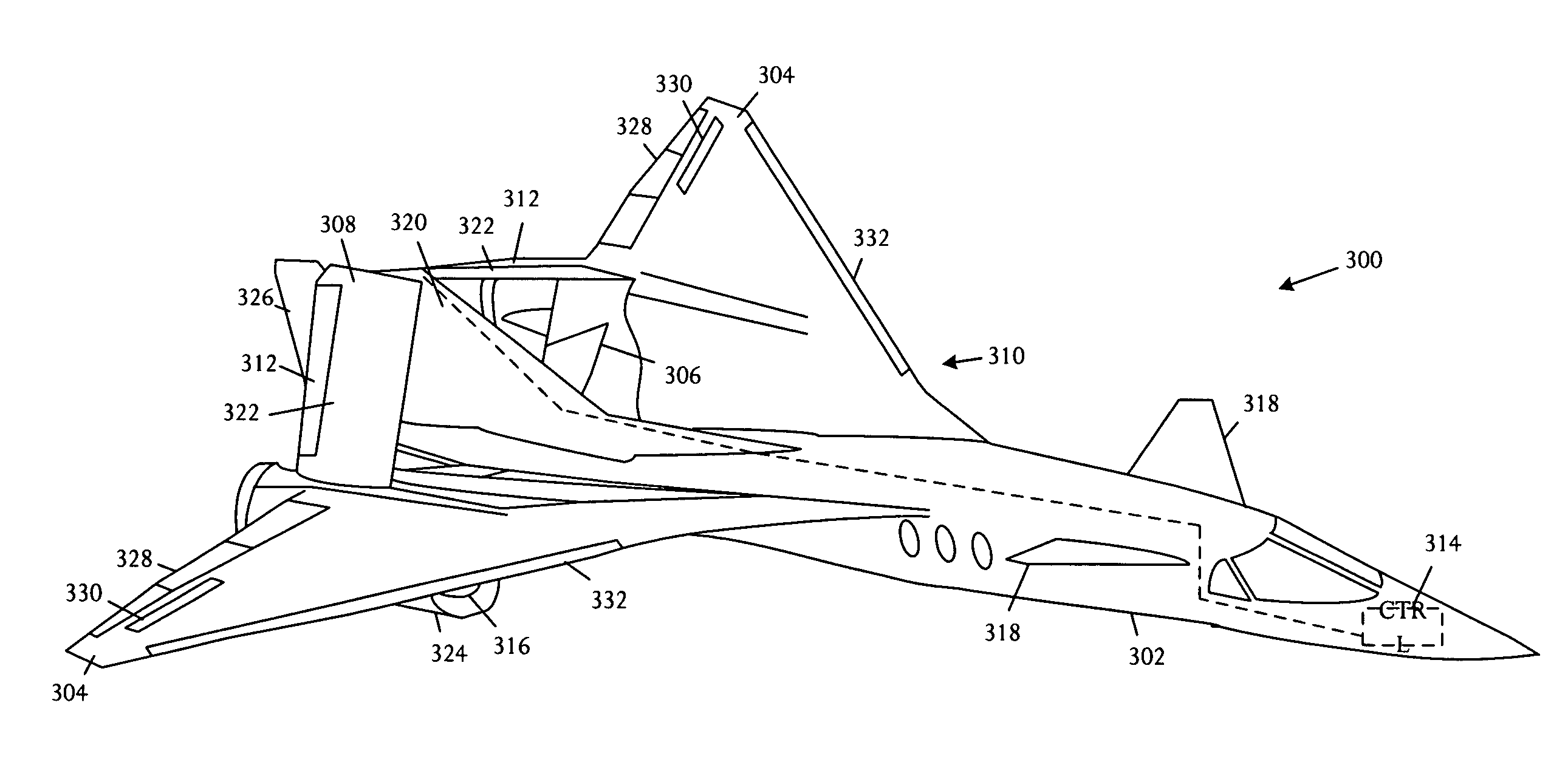
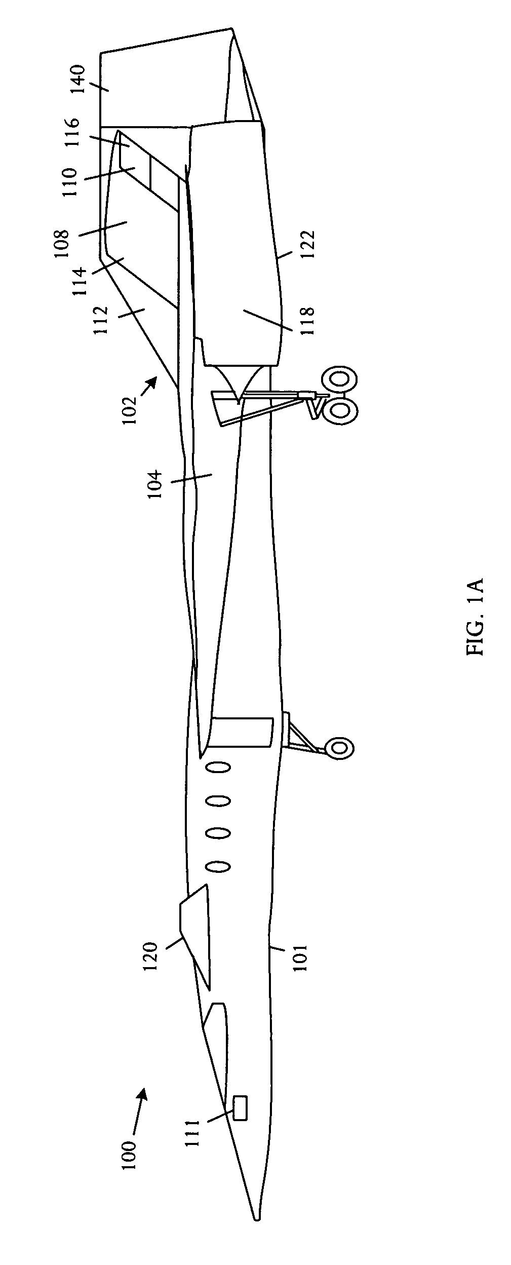
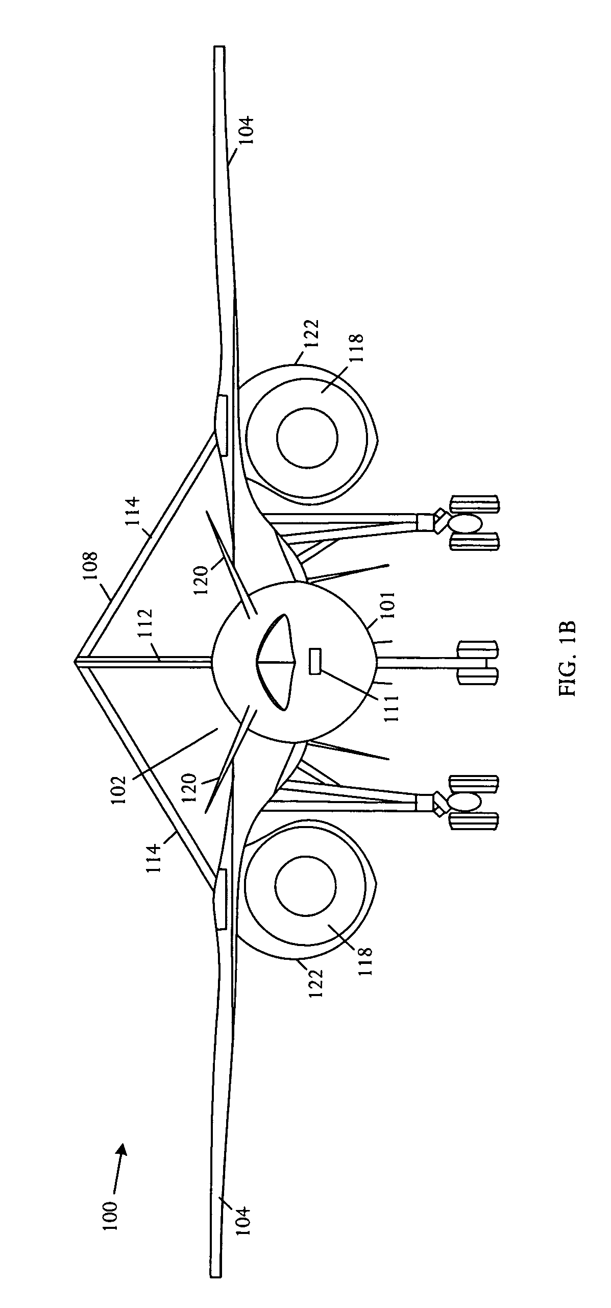
[0027]The aircraft embodiment 100 further comprises engines 118 coupled to the aft portion of the wing lower surface with the inverted V-tail geometry empennage 108 coupled to the wing in the braced wing configuration carrying lift at the aft portion of the aircraft 100 on a high mounted tail 108. The length of the aircraft is effectively extended for shock waves below the aircraft 100, thereby further reducing sonic boom. The inverted V-tail 108 carries tail lift high to maintain a continuous lift distribution and structurally bracing the wing 104 and engines 118.

[0028]Referring to FIG. 1C, control effectors are shown for the supersonic aircraft 100. Two sets of surfaces are available for pitch control including canards 120 and ruddervators 116. Roll control uses ailerons 128 and high speed spoilers 130. Yaw control is supplied by a rudder 140, ruddervators 116, and differential canard 120.

[0029]In combination with the canards 120, the supersonic aircraft 100 has multiple stability...

embodiment 900

[0062]Referring to FIG. 9, a schematic block diagram shows an example a flight control actuation architecture embodiment 900 that can be used to control effectors in the empennage to operate in a drag reduction mode and, conversely, to increase drag in operation as a speedbrake. In the illustrative example, primary flight control actuation uses “Fly-by-Wire” dual tandem linear hydraulics with triple electronic redundancy. Dual tandem actuation 902 is powered by two independent hydraulic systems 904 and 906 and sized for full rated performance based on a single system operation. The flight control system is closed-loop and commanded by the Vehicle Management Computers 908. The flight control system 900 performs control law implementations to produce aircraft handling qualities throughout flight. The system 900 can implement outer loop control modes such as Autopilot, Autolanding, and Auto collision avoidance control. The flight control actuation system 900 can also execute system int...


PUM


Abstract

A supersonic aircraft comprises a fuselage extending forward and aft along a longitudinal axis, the fuselage having a lower surface and an upper surface, a highly swept low aspect ratio wing coupled to the fuselage and having a forward leading edge and an aft trailing edge, an effector flap coupled to the wing trailing edge, and a tail empennage. The tail empennage is coupled to the fuselage aft of the wing on the fuselage upper surface in a position high relative to the wing. The tail empennage forms a channel region subject to complex shock patterns at transonic conditions. The aircraft further comprises an effector coupled to the tail empennage and a controller coupled to the effector flaps and the effectors. The controller further comprises a control process that reduces drag through channel relief by deflecting both the effector flap down and the effector up.

Description

BACKGROUND OF THE INVENTION[0001]The global economy makes long range business travel more essential than ever. However, other than Concorde, with presence declining as transatlantic flights have discontinued, the pace of business travel remains at 1960's-era speeds. Technology advances have produced longer range, safer, and more comfortable aircraft—but not faster flights.[0002]Supersonic overland capability and range are drivers of market potential for aircraft in the commercial and business sector. Buyers of supersonic commercial aircraft are expected to be from entities such as corporations, governments and government agencies, and high net-worth individuals. Most operators are expected to be large organizations, for example corporations and governments, with sophisticated flight departments that can manage multiple aircraft types. Flights are expected to depart and arrive in a wide range of environments, from large international and national airports to small local airfields or ...

Claims


Application Information

Patent Timeline
Patent Type & Authority Patents(United States)
IPC IPC(8): B64C9/00B64C5/02B64C23/00B64C13/00B64C39/06B64C23/04B64C13/50B64C30/00B64C5/00B64C39/00B64C3/00B64C3/16
CPCB64C3/16B64C5/02B64C9/00B64C13/503B64C23/04B64C30/00B64C39/068Y02T50/12Y02T50/32B64C13/505Y02T50/10Y02T50/30
Inventor CHANG, MINGMEZA, VICTORMORGENSTERN, JOHN M.ARSLAN, ALAN E.
Owner SUPERSONIC AEROSPACE INT
Why Eureka
Try Eureka