Sealing apparatus and a rolling bearing and a clutch apparatus provided therewith

a technology of sealing apparatus and rolling bearing, applied in the direction of magnetically actuated clutches, mechanical actuators, mechanical actuators, etc., can solve the problems of reducing sealing performance, and achieve the effect of improving sealing performance and reducing deformation

Inactive Publication Date: 2005-07-26
NTN CORP
View PDF15 Cites 16 Cited by
  • Summary
  • Abstract
  • Description
  • Claims
  • Application Information

AI Technical Summary

Benefits of technology

[0012]It is, therefore, an object of the present invention to provide a sealing apparatus which can reduce the deformation due to the press fit of the sealing apparatus and thus can obtain a desirable improved sealing performance.
[0014]According to the invention, it is possible to suppress the deformation of the core member during the press fit. Thus, it is possible to maintain the desirable sealing performance without causing change of the lip interference.
[0016]Additionally, a rolling bearing includes outer ring formed with a raceway on the inner circumferential surface. An inner ring is formed with a raceway on the outer circumferential surface arranged opposite to the raceway of the outer ring. A plurality of rolling elements are arranged between the raceways of the outer and inner rings. The above sealing apparatus are arranged in end annular spaces between the outer and inner rings. Accordingly, the rolling bearing ensures prevention of the leakage of grease sealed within the bearing and the immigration of dust into the bearing from the outside even though it is laid under severe circumstances.
[0018]Accordingly, the rolling bearing ensures prevention of the leakage of grease sealed within the clutch apparatus and the immigration of dust into the clutch apparatus from the outside and also it is possible to suppress the influence to the sealing apparatus even though the deformation of the inner or outer member due to the engagement of the engaging elements.

Problems solved by technology

Change of the lip interference and / or the warp caused in the upstanding portions often cause the reduction of the sealing performance.

Method used


Image

  • Sealing apparatus and a rolling bearing and a clutch apparatus provided therewith
  • Sealing apparatus and a rolling bearing and a clutch apparatus provided therewith
  • Sealing apparatus and a rolling bearing and a clutch apparatus provided therewith

Examples


Embodiment Construction

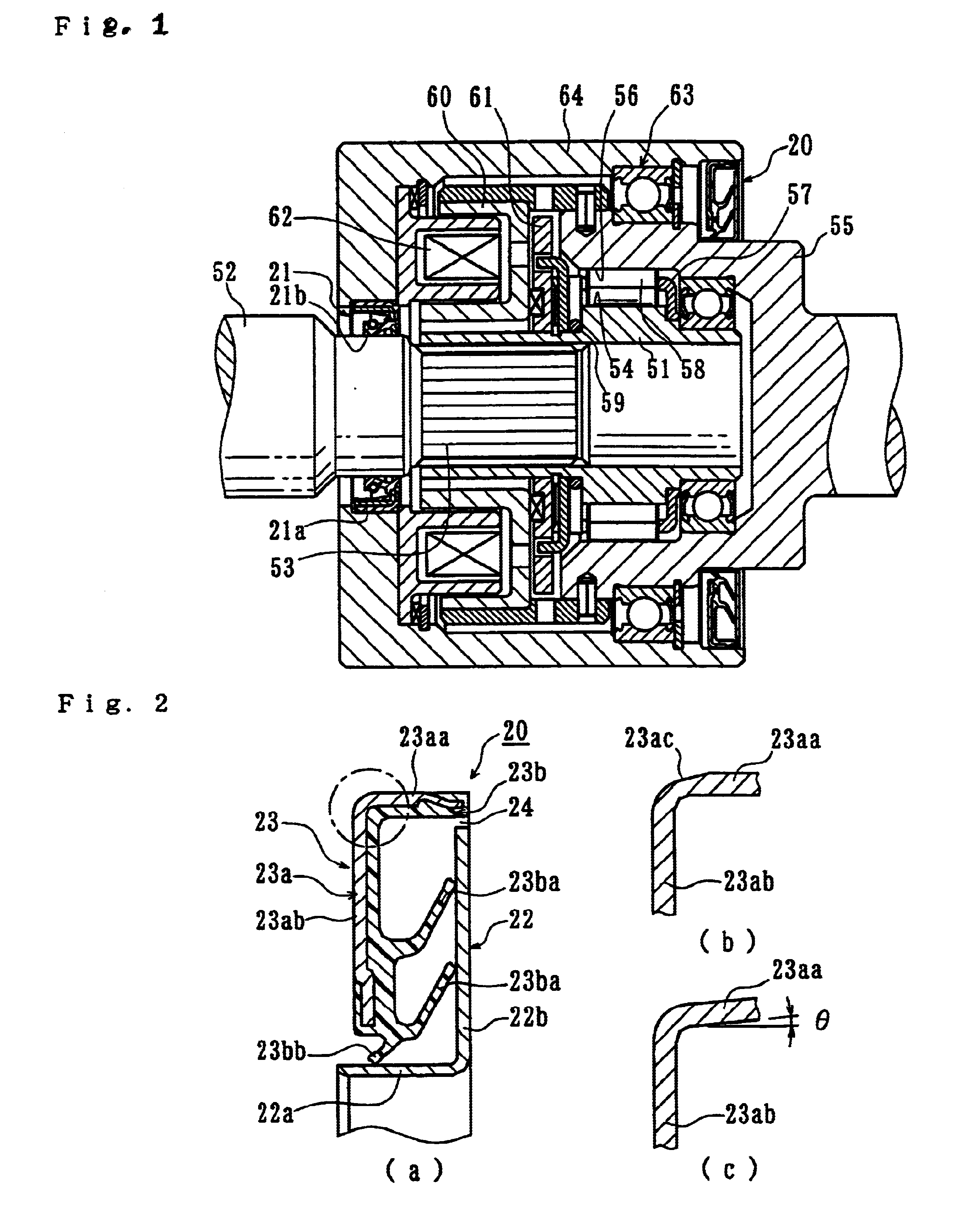
[0028]The present invention will be described with reference to FIGS. 1 through 3 of the accompanying drawings. FIG. 1 is a longitudinal cross-section view showing a clutch apparatus with the sealing apparatus 20 and 21 of the present invention. Since the clutch apparatus itself shown in FIG. 1 is same as that shown in FIG. 4, the same reference numerals are used for designating the same parts.

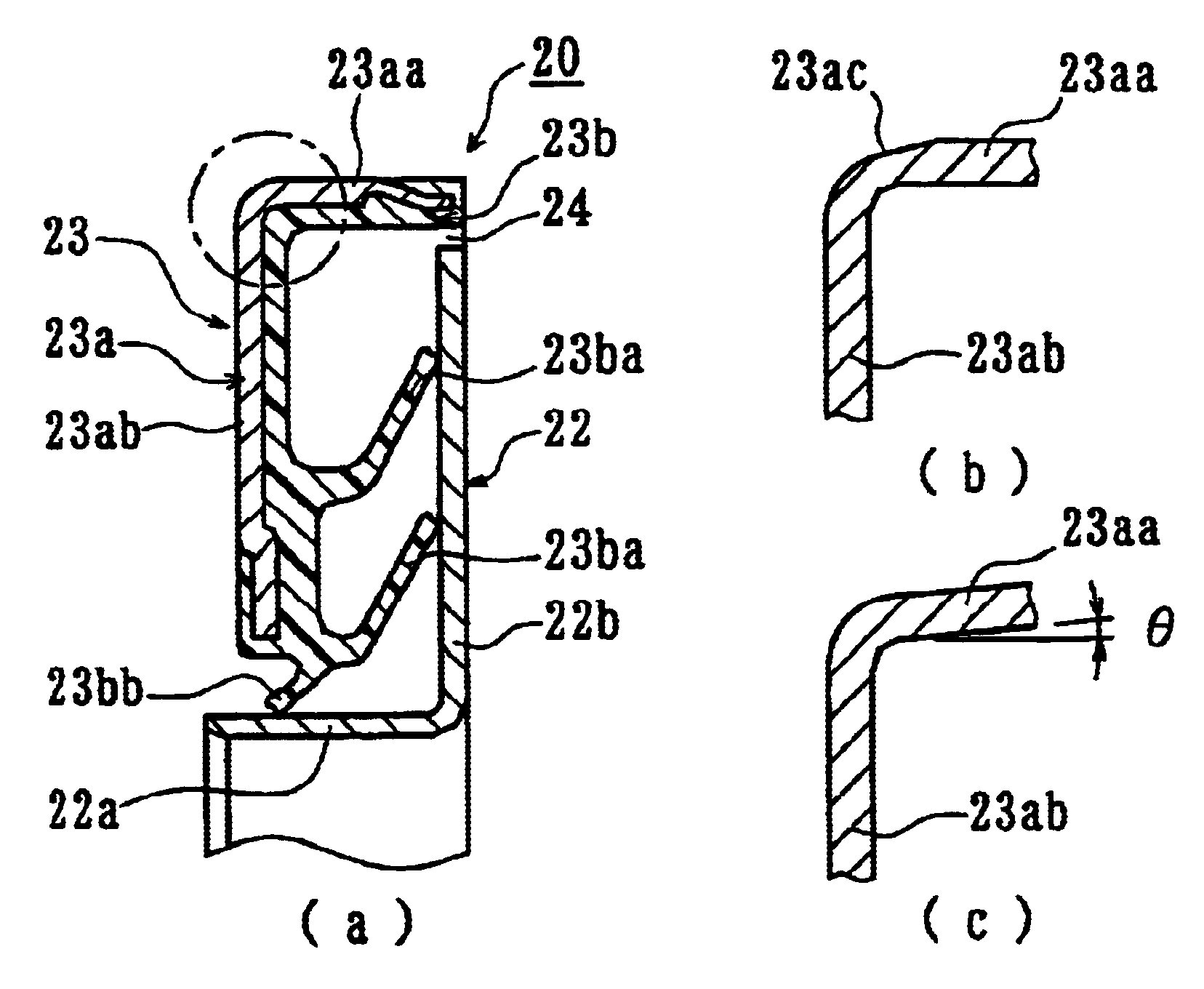
[0029]The sealing apparatus 20 of the present invention, as shown in FIG. 2(a), has a slinger 22 to be arranged on an inner circumferential side (the outer member 55) in the illustrated embodiment. A seal member 23 is to be arranged on an outer circumferential side of the housing 64 in the illustrated member. The slinger 22 is formed as a substantially L-shaped cross-section member including a cylindrical portion 22a to be fitted in the outer member 55 and an upstanding portion 22b radially extending from one end of the cylindrical portion 22a. The sealing member 23 is adapted to be arranged o...


PUM


Abstract

A sealing apparatus (20) has a slinger (22) with a substantially L-shaped cross-section including a cylindrical portion (22a) to be fitted on a member of rotational side and an upstanding portion (22b) radially extending from one end of the cylindrical portion (22a). The apparatus also has a core member (23a) of a substantially L-shaped cross-section including a cylindrical portion (23aa) to be fitted in a member of stationary side and an upstanding portion (23ab) radially extending from one end of the cylindrical portion. Further included is a sealing element (23b) including one ore more side lips (23ba) and (23ba) adapted to be slidably contacted with the upstanding portion (22b) of the slinger (22) and one or more radial lips (23bb) adapted to be slidably contacted with the cylindrical portion (22a) of the slinger (22). An interference of a portion of the cylindrical portion (23aa) and / or (22a) of the core member (23a) and / or the slinger (22) near the upstanding portion (23ab) and / or (22b) is formed smaller than that of the other portion of the cylindrical portion (23aa) and / or (22a) of the core member (23a) and / or the slinger (22).

Description

CROSS-REFERENCE TO RELATED APPLICATIONS[0001]This application claims priority to Japanese Patent Application Nos. 2001-304916 filed Oct. 1, 2001, which application is herein expressly incorporated by reference.FIELD OF THE INVENTION[0002]The present invention relates to a sealing apparatus and more particularly to a sealing apparatus used, for example, for a rolling bearing and a clutch apparatus.BACKGROUND OF THE INVENTION[0003]There is a clutch apparatus of the prior art having the sealing apparatus of this kind, for example, as shown in FIG. 4.[0004]A clutch apparatus 50 includes inner member 51 which engages an input shaft 52 via a serration 53 and has a plurality of cam surfaces 54 on the outer circumferential surface. A hollow outer member 55 is arranged coaxially with the inner member 51 and has a cylindrical surface 56 formed on an inner circumferential surface. An annular wedge-shaped space is formed by a cam surface 54 of the inner member 51 and a cylindrical surface 56 of...

Claims


Application Information

Patent Timeline
Patent Type & Authority Patents(United States)
IPC IPC(8): F16C33/78F16C33/76F16D41/00F16D41/08F16D27/00F16J15/32F16D27/112F16J15/3232
CPCF16C33/7879F16D28/00F16C33/783F16J15/3264F16D41/088F16C19/184F16D2023/123F16D23/12F16D27/112
Inventor YASUI, MAKOTOSATO, KOJI
Owner NTN CORP
Why Eureka
Try Eureka