Cutter insert and milling tool

a cutter insert and milling tool technology, applied in the field of cutter inserts for milling tools, can solve the problems that cutter inserts are simple and cannot be readily used in corner milling cutters, and achieve the effect of convenient use and simple manufactur

Active Publication Date: 2005-07-26
WALTER AG
View PDF8 Cites 92 Cited by
  • Summary
  • Abstract
  • Description
  • Claims
  • Application Information

AI Technical Summary

Benefits of technology

[0009]The cutter insert according to the invention has a base body which is twisted in two directions, that is, it has a double twist. Thus, the cutter insert has no longer a planar base surface, but a base surface which is of the same shape as the top surface. In case the cutter insert is turned, for example, about a longitudinal axis or a transverse axis, so that the base surface arrives in a position which was previously assumed by the top surface, then the top surface is identical in all essential aspects to the base surface that has occupied the same position previously, and vice versa. The reversible cutter insert is thus rotationally symmetrical with respect to at least one symmetry axis passing transversely through the securing opening. In this manner the reversible cutter insert may be turned at its location not only through 180° about an axis which passes coaxially through the securing opening (and which is also a symmetry axis), but additionally about at least one symmetry axis oriented transversely to the securing opening. As a result, instead of only two cutting edges or cutting edge pairs that have been accessible heretofore, a total of four are now accessible which doubles the service life of the inventive cutter insert as compared to conventional cutter inserts....

Problems solved by technology

Such simple cutter inserts, however, cannot be readily used in corne...

Method used


Image

  • Cutter insert and milling tool
  • Cutter insert and milling tool
  • Cutter insert and milling tool

Examples


Embodiment Construction

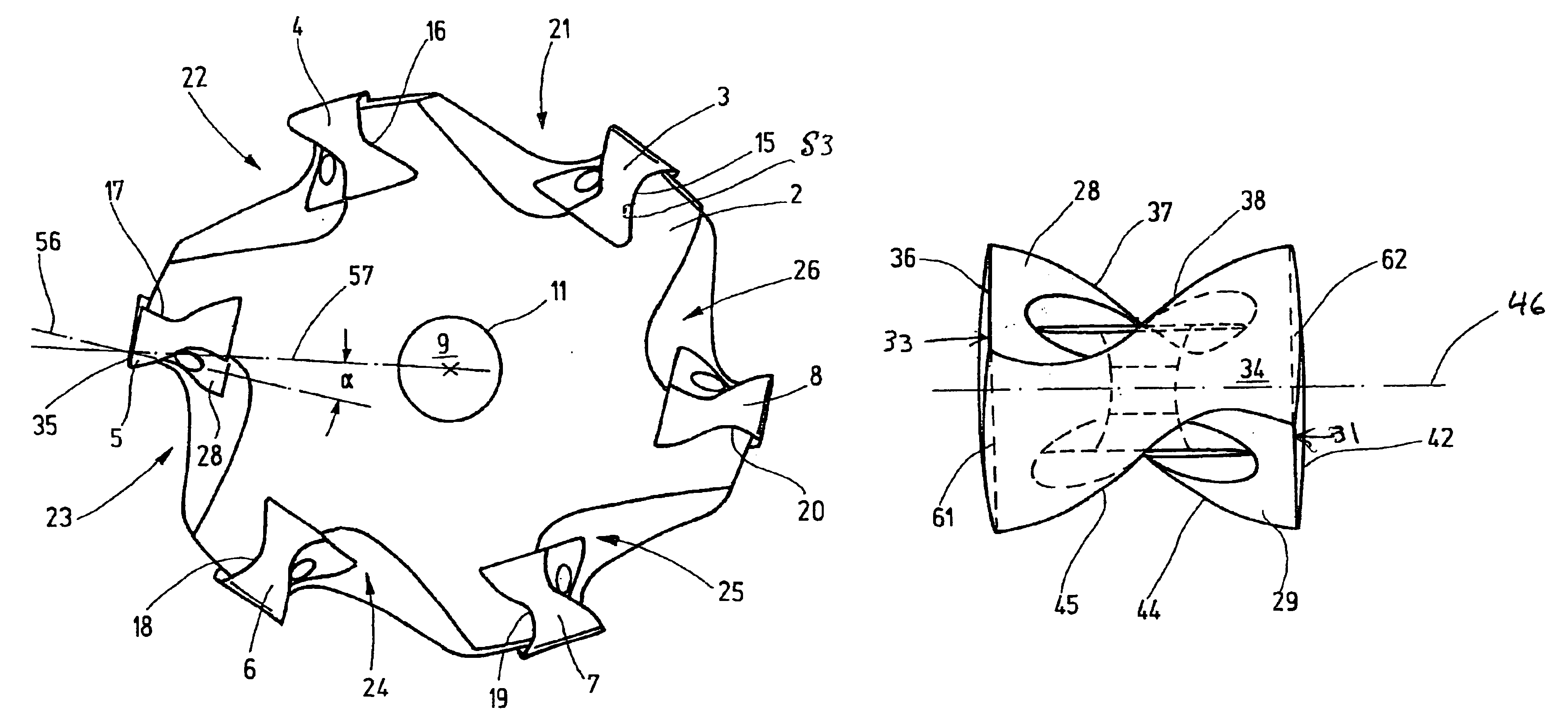
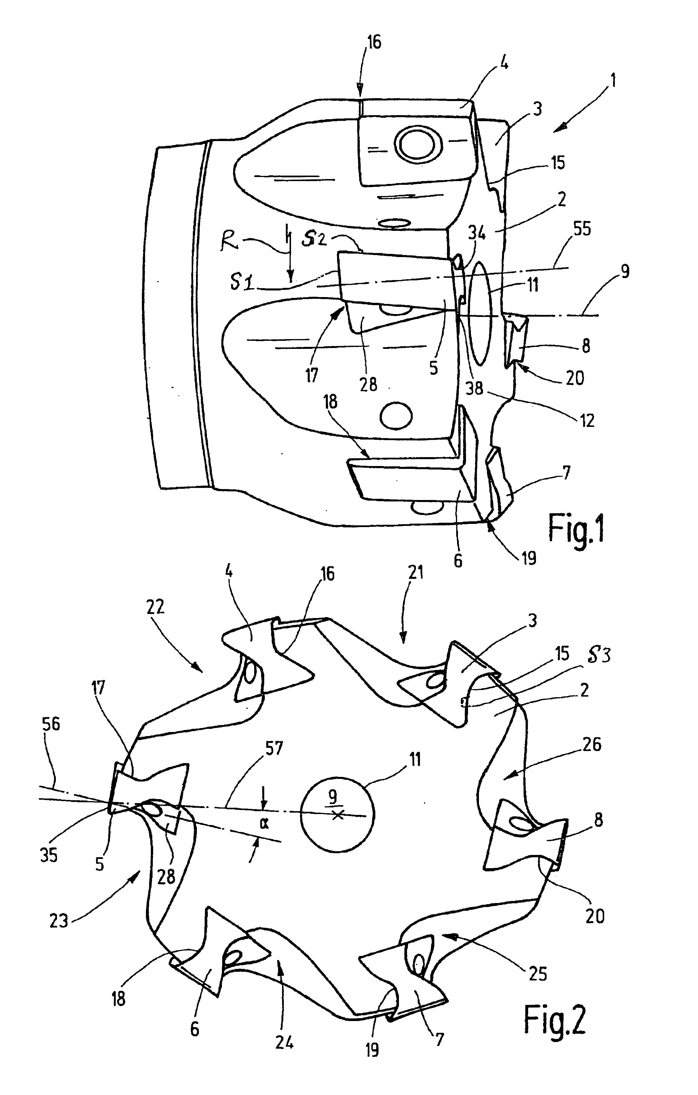
[0023]FIG. 1 shows a milling tool 1 comprising a tool body 2 and cutter inserts 3, 4, 5, 6, 7, 8 secured thereto. The cutter inserts 3 to 8 are of identical construction, and consequently, the ensuing description of the cutter insert 3 applies to all the other cutter inserts 4 through 8.

[0024]The tool body 2 is designed for rotation in a direction R about a rotary axis 9 and has a securing opening 11 which is concentric to the rotary axis 9. The milling tool 1 is corner milling cutter; its cutter inserts 3 to 8 have active cutting edges both on the end face 12 and along the periphery of the milling tool 1. The cutter inserts 3 to 8 are disposed in respective insert seats 15 to 20 provided in respective pockets 21 to 26 of the tool body 2, as particularly well seen in FIG. 2.

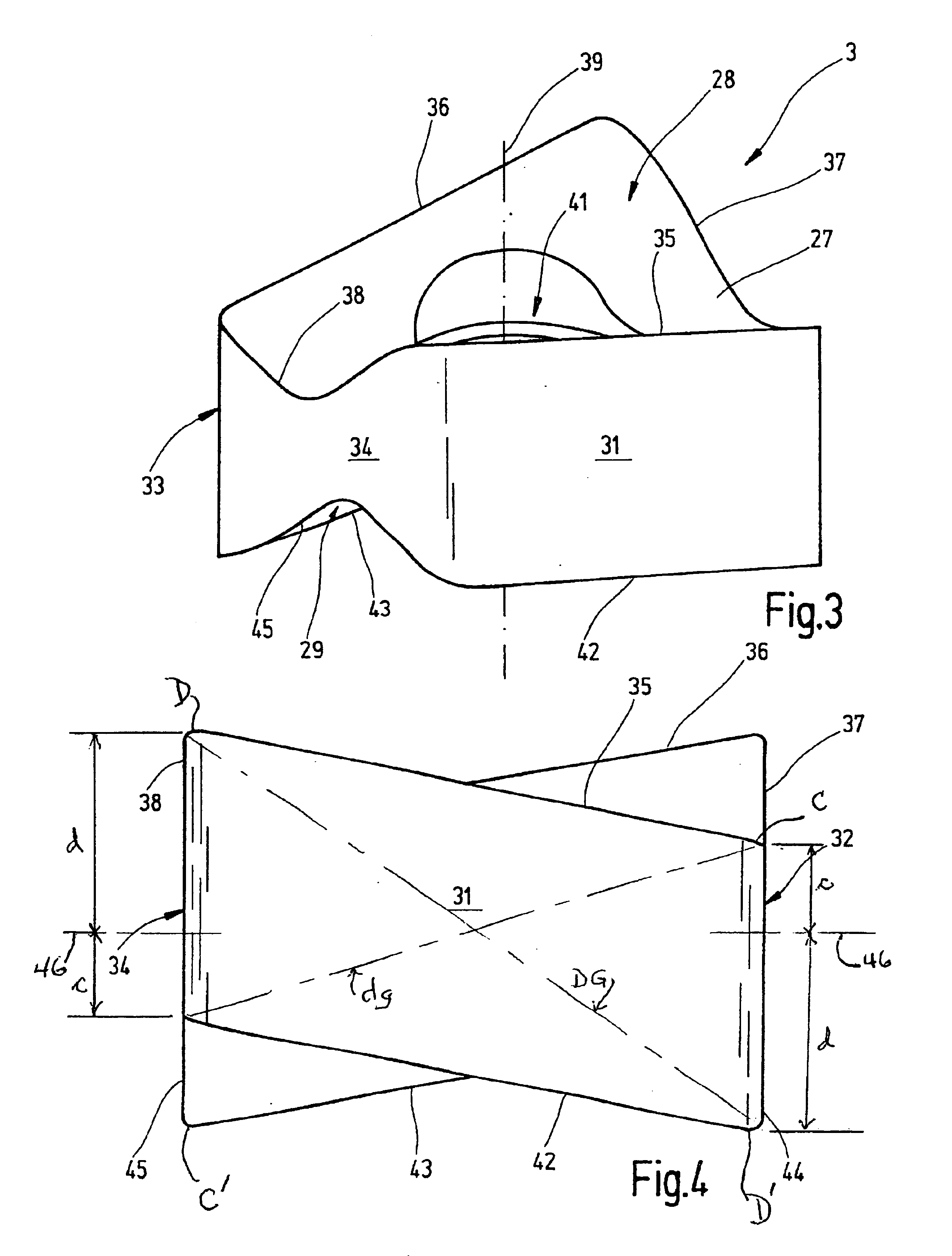
[0025]In the description which follows, the structure of the cutter insert 3 will be explained in conjunction with FIGS. 3 to 7. The cutter insert 3 has a base body which, as observed in the top plan view of FIG....


PUM


Abstract

A cutter insert for milling tools includes a base body having a base surface, a top surface, and four side surfaces. The four side surfaces, together with each of the base surface and the top surface, define respective cutting edges. The base body is twisted about each of two perpendicular, coplanar axes of the base body. Each side surface has two opposite corner edges that are offset from one another in a direction parallel to a center axis of the base body.

Description

[0001]This application claims priority under 35 U.S.C. §§ 119 and / or 365 to patent application Serial No. 10312922.7 filed in Germany on Mar. 22, 2003 the entire content of which is hereby incorporated by reference.BACKGROUND OF THE INVENTION[0002]The invention relates to a cutter insert for milling tools, particularly corner milling cutters, as well as a milling tool provided with such a cutter insert.[0003]As a rule, milling tools are provided with cutter inserts which may be secured in their respective insert seat in several orientations. In this manner several cutting edges provided on the cutter insert may become active in succession, whereby the service life of the cutter insert is extended. The geometrical configuration of a cutter insert significantly affects the chip formation. For example, in most cases a positive rake angle is desired, both at the peripheral cutting edges and at the frontal cutting edges of a milling tool. As a rule, these desiderata are taken into accoun...

Claims


Application Information

Patent Timeline
IPC IPC(8): B23C5/16B23C5/22B23C5/20B23C5/06
CPCB23C5/2221B23C2200/083B23C2200/123Y10T407/23B23C2200/203B23C2200/361Y10T407/1908B23C2200/162B23C5/2213B23C5/205
Inventor DUERR, HANS-PETERSTABEL, THORSTEN
Owner WALTER AG
Why Eureka
Try Eureka