Deformable intraocular corrective lens

Inactive Publication Date: 2005-07-26
THINOPTX
View PDF41 Cites 34 Cited by
  • Summary
  • Abstract
  • Description
  • Claims
  • Application Information

AI Technical Summary

Benefits of technology

[0014]The present invention is a deformable intraocular contact lens constructed from PMMA for rolled or folded insertion into the human eye to correct common vision problems. The PMMA is deformable because all portions of the lens are manufactured to a thickness which is within a predetermined range of thicknesses. More particularly, at the first end of the range, the thickness of the lens is less than a maximum material thickness, the threshold under which the PMMA is flexible. At the second end of the range, the thickness of the lens is also greater than a minimum material thickness, the threshold abov

Problems solved by technology

However, using an intraocular lens for vision correction is currently problematic.
Unfortunately, the making of the incision causes astigmatism of the cornea.
However, currently designed PMMA lenses are rigid and too brittle to be rolled or folded.
This thickness is too thin for use in a conventional contact lens because of the lens' optics requirements.
However, if not handled very carefully, the lower-weight acrylic will crease, renderin

Method used


Image

  • Deformable intraocular corrective lens
  • Deformable intraocular corrective lens
  • Deformable intraocular corrective lens

Examples


second embodiment

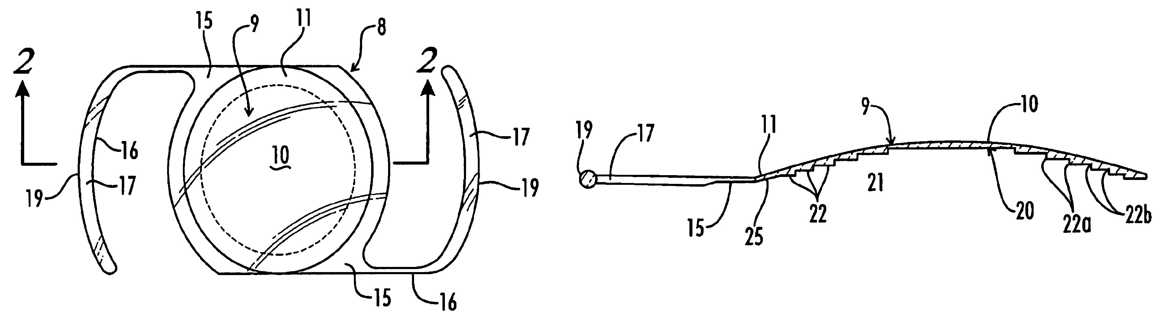
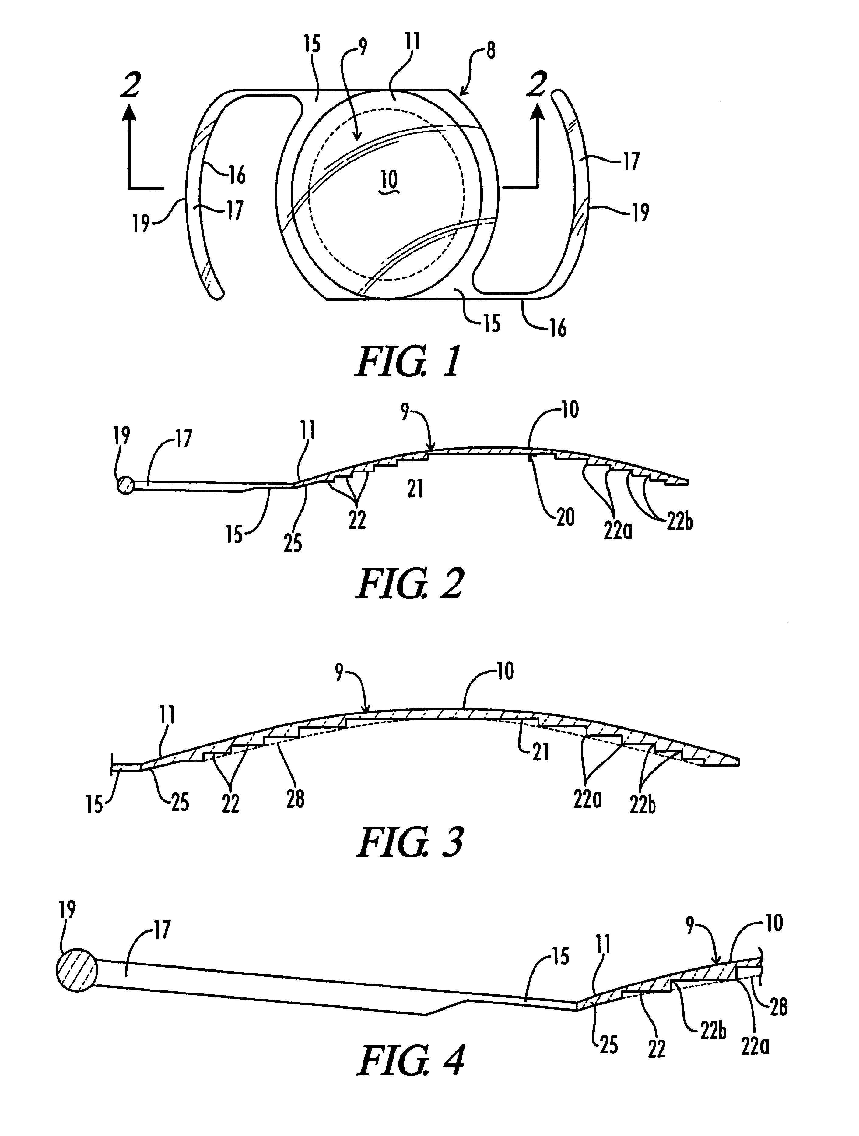
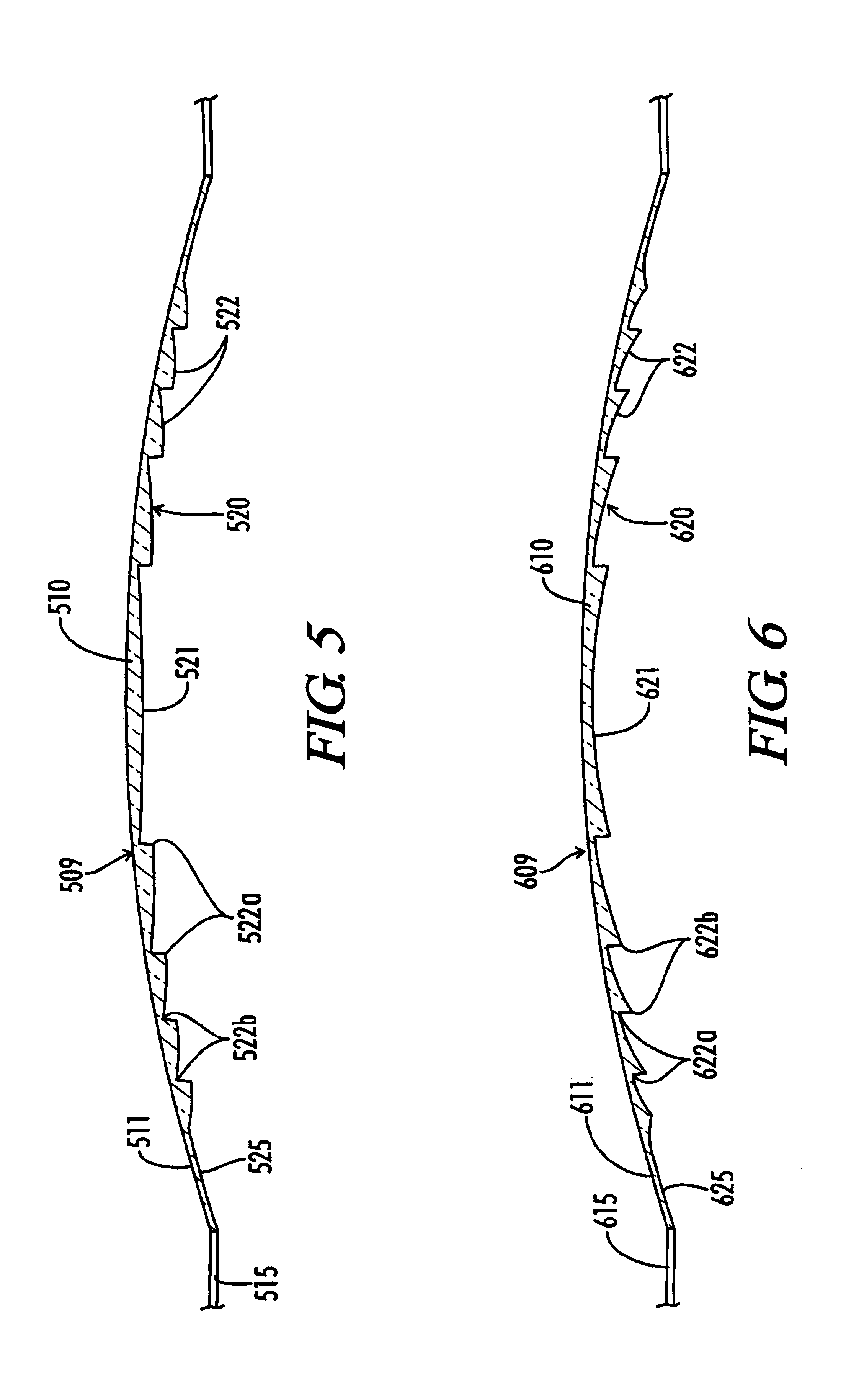
[0045]FIG. 5 is a cross-sectional fragmented view of the invention. In this alternate embodiment, the anterior lenticular surface 510 of the optic portion 509 is of the same convex shape as in the previously described embodiment. The posterior surface 520 comprises a central disk 521 which is surrounded by a plurality of annular rings 522. The central disk 521 and series of annular rings 522 form a series of radial steps across the posterior surface 520 to maintain a close proximity to the lenticular surface 510.

[0046]In this embodiment, the surfaces of the central disk 521 and each of the annular rings 522 are convex. The thickness of the central disk 521 at the apex of the lenticular surface 10 is less than or equal to the predetermined maximum thickness. The thickness of the periphery of the central disk 521 is greater than or equal to a predetermined minimum thickness.

[0047]Each annular ring 521 has an external point 522a and an internal diameter 522b. The thickness of the conta...

third embodiment

[0048]FIG. 6 is a cross-sectional fragmented view of the invention. In this alternate embodiment, the anterior lenticular surface 610 of the optic portion 609 is of the same convex shape as in the previously described embodiments. The posterior surface 620 comprises a central disk 621 which is surrounded by a plurality of annular rings 622. The central disk 621 and series of annular rings 622 form a series of radial steps across the posterior surface 620 to maintain a close proximity to the lenticular surface 610.

[0049]In this embodiment, the surfaces of the central disk 621 and each of the annular rings 622 are concave. The thickness of the central disk 621 at the periphery of the central disk 621 is less than or equal to the predetermined maximum thickness. The thickness of the lens between the apex of the lenticular surface 610 and the central disk 621 is greater than or equal to a predetermined minimum thickness.

[0050]Each annular ring 621 has an internal diameter 622a and an ex...


PUM


Abstract

A deformable, artificial intraocular contact lens for implantation into the human eye to correct normal-vision problems. The lens may be positioned posteriorly from the iris, resting against the anterior surface of the posterior capsule's natural lens. Alternatively, the lens may be positioned in the anterior chamber of the eye. The implanted lens works in conjunction with the cornea and natural lens to provide proper vision, as a substitute for regular contact lens, spectacles, and radial keratotomy. The lens may be designed from a rigid or semi-rigid material. Due to the thinness of the structure, the lens may be rolled and inserted into the eye, minimizing both the length of the corneal incision and the stretching of the cornea.

Description

[0001]This application is a continuation application of U.S. patent application Ser. No. 09 / 441,425 filed Nov. 16, 1999, now U.S. Pat. No. 6,488,707, for “Method of Implanting a Deformable Intraocular Corrective Lens,” which is hereby incorporated by reference, which is a divisional application of U.S. patent application Ser. No. 08 / 914,767 filed Aug. 20, 1997, now U.S. Pat. No. 6,096,077 for “Deformable Intraocular Corrective Lens,” which is hereby incorporated by reference.BACKGROUND OF THE INVENTION[0002]1. Field of the Invention[0003]The present invention relates to a deformable intraocular contact lens to correct vision problems, which lens is inserted into the eye anterior to the natural lens and has a functional design which minimizes cutting or stretching of the cornea to do so.[0004]2. Description of the Related Art[0005]Doctors trained in ophthalmology routinely surgically extract cataract-impaired lenses from patients' eyes and subsequently implant artificial lenses to pr...

Claims


Application Information

Patent Timeline
IPC IPC(8): A61F2/16
CPCA61F2/1613A61F2/1602A61F9/007A61F2002/1681
Inventor CALLAHAN, WAYNE B.CALLAHAN, JEFFREY S.
Owner THINOPTX
Why Eureka
Try Eureka