
Constant pressure magnetically preloaded FDB motor

a magnetically preloaded, constant-pressure technology, applied in the direction of sliding contact bearings, record information storage, instruments, etc., can solve the problems of limiting the density of data tracks and the overall performance of the disc drive system, misalignment between data tracks and read/write transducers, and reducing the working area of journal bearings, and maintaining radial alignment and/or stiffness

Inactive Publication Date: 2005-07-26
SEAGATE TECH LLC
View PDF9 Cites 15 Cited by
  • Summary
  • Abstract
  • Description
  • Claims
  • Application Information

AI Technical Summary

Benefits of technology

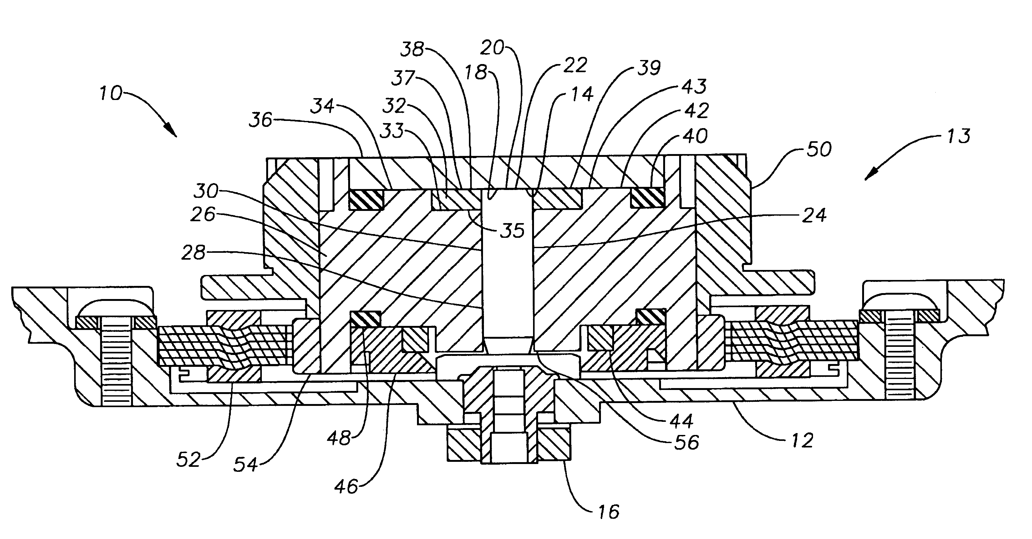
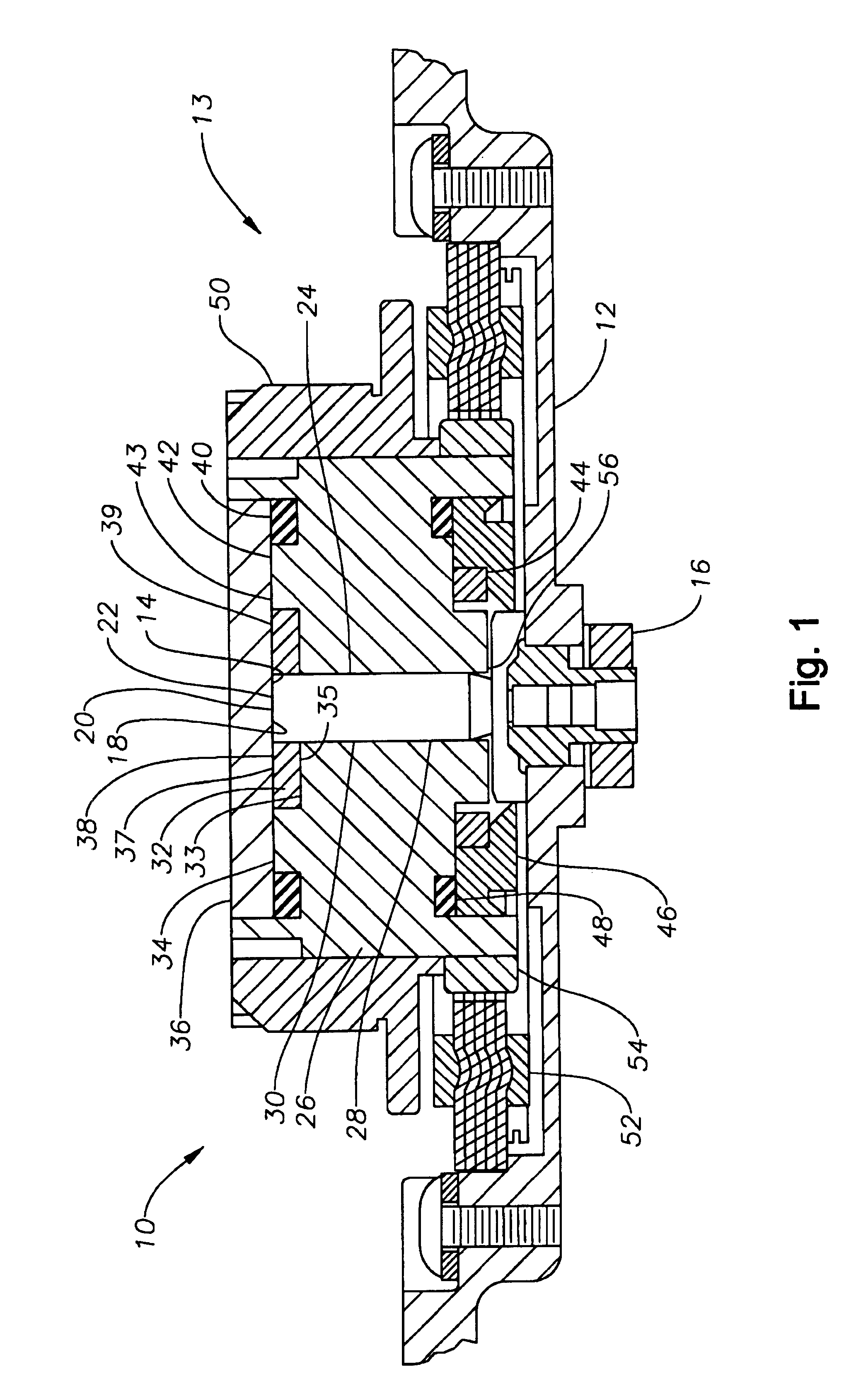
[0011]More particularly, the present invention is intended to provide a fluid bearing assembly in which the temperature influence on power requirements, and stiffness, is diminished.
[0012]These and other advantages and objectives are achieved by providing a fluid bearing design wherein a fluid bearing supports the shaft for rotation, with its positioning being axially compensated by a magnetic preload. By this combination, as the motor speeds up and heats up, which would otherwise cause the fluid pressure in gap to change, the magnetic preload maintains the pressure in the fluid between relatively rotating rotor and stator.
[0013]The shaft may be supported for rotation by a conical bearing rotating within a sleeve. To prevent misalignment of the rotor and stator as the motor heats up and fluid viscosity changes, a magnetic preload is established; in a preferred embodiment, the magnetic preload is achieved using a magnetic back iron aligned with the stator magnet, the magnetic back iron being supported from the base. The shaft may further include a lower journal bearing for maintaining radial alignment and / or stiffness.
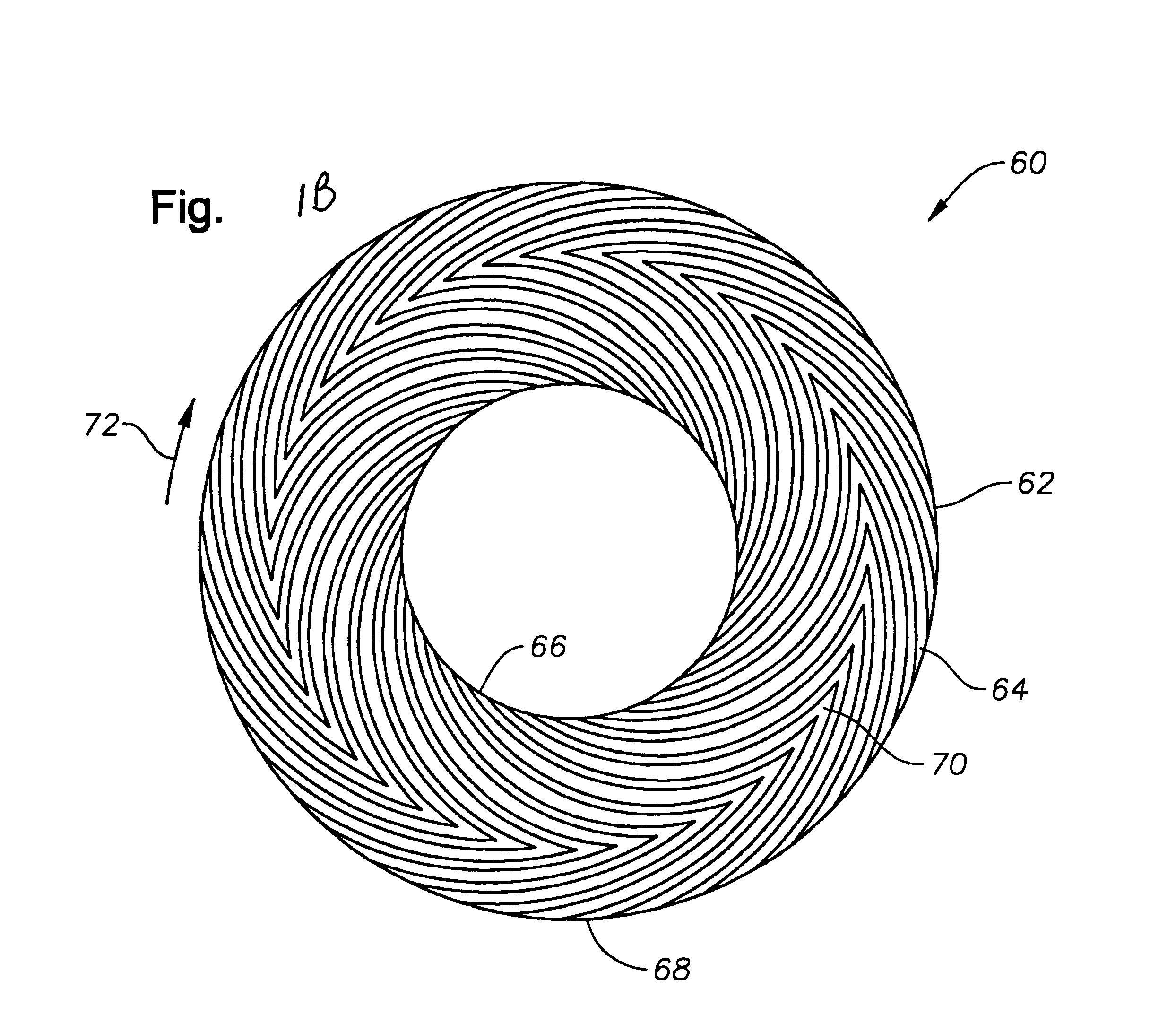
[0014]A shaft may be supported for rotation relative to a sleeve by a combination of journal bearing and thrust bearing whose gaps are connected and grooved to cooperate. The bearing system includes a magnetic preload at the end of the shaft distal from the journal bearing / thrust bearing combination, the magnetic force balancing the spiral groove thrust bearing to maintain the bearing support for the shaft and the load (including hub and disc) that it supports. Further, the journal bearing balances against the thrust bearing so that as fluid is drawn further into the thrust bearing, it is withdrawn from the journal bearing to reduce the working area of the journal bearing. A reservoir terminating in a capillary seal also provided on the far side of the thrust bearing from the journal bearing. This design allows the journal bearing to drain itself as the thrust bearing spins up and its pressure increases so that the pressure of the journal bearing matches the thrust bearing.
[0016]It can further be seen that the design will be relatively easy to assemble requiring simply an injection of oil into the hub to fill the single gap between the hub / shaft combination and the sleeve.

Problems solved by technology

First is the problem of vibration generated by the balls rolling on the bearing raceways.
This vibration results in misalignment between the data tracks and the read / write transducer.
This source of vibration limits the data track density and the overall performance of the disc drive system.
Vibration results in misalignment between the data tracks and the read / write transducer.
Vibration also limits the data track density and the overall performance of the disc drive system.
Further, mechanical bearings are not always scalable to smaller dimensions.
This is a significant drawback, since the tendency in the disc drive industry has been to continually shrink the physical dimensions of the disc drive unit.
Thus, as the temperature changes, the power required to spin the motor will vary, if the gap remains constant; further, the stiffness of the system will diminish as the system heats and fluid viscosity diminishes.

Method used


Image

  • Constant pressure magnetically preloaded FDB motor
  • Constant pressure magnetically preloaded FDB motor
  • Constant pressure magnetically preloaded FDB motor

Examples


Embodiment Construction

[0023]Reference will now be made in detail to exemplary embodiments of the invention, examples of which are illustrated in the accompanying drawings. While the invention will be described in conjunction with these embodiments, it is to be understood that the described embodiments are not intended to limit the invention solely and specifically to only those embodiments, or to use solely in the disc drive which is illustrated. On the contrary, the invention is intended to cover alternatives, modifications and equivalents which may be included within the spirit and scope of the invention as defined by the attached claims. Further, both hard disc drives, in which the present invention is especially useful, and spindle motors, where the invention is also especially useful are both well known to those of skill in this field. In order to avoid confusion while enabling those skilled in the art to practice the claimed invention, this specification omits such details with respect to known ite...


PUM

PropertyMeasurementUnit
viscosityaaaaaaaaaa
axial pressureaaaaaaaaaa
temperatureaaaaaaaaaa

Abstract

The shaft may be supported for rotation by a conical bearing rotating within a sleeve. To prevent misalignment of the rotor and stator as the motor heats up and fluid viscosity changes, a magnetic preload is established; in a preferred embodiment, the magnetic preload is achieved using a magnetic back iron aligned with the stator magnet, the magnetic back iron being supported from the base. The shaft may further include a lower journal bearing for maintaining radial alignment and / or stiffness.A shaft may be supported for rotation relative to a sleeve by a combination of journal bearing and thrust bearing whose gaps are connected and grooved to cooperate. The bearing system includes a magnetic preload at the end of the shaft distal from the journal bearing / thrust bearing combination, the magnetic force balancing the spiral groove thrust bearing to maintain the bearing support for the shaft and the load (including hub and disc) that it supports. Further, the journal bearing balances against the thrust bearing so that as fluid is drawn further into the thrust bearing, it is withdrawn from the journal bearing to reduce the working area of the journal bearing. A reservoir terminating in a capillary seal also provided on the far side of the thrust bearing from the journal bearing. This design allows the journal bearing to drain itself as the thrust bearing spins up and its pressure increases so that the pressure of the journal bearing matches the thrust bearing.

Description

CROSS REFERENCE TO A RELATED APPLICATION[0001]This application claims priority to two provisional applications, Ser. No. 60 / 363,986 filed Mar. 12, 2002, entitled CONSTANT PRESSURE MAGNETICALLY PRELOADED FDB MOTOR invented by Norbert Steven Parsoneault, Troy Michael Herndon and Jim-Po Wang, and provisional application Ser. No. 60 / 368,675, filed on Mar. 29, 2002, entitled CONSTANT PRESSURE CONICAL FDB invented by Norbert Steven Parsoneault and Troy Michael Herndon and incorporated herein by reference.FIELD OF THE INVENTION[0002]The present invention relates to the field of fluid dynamic bearings, and more particularly to fluid bearings which are less temperature dependent.BACKGROUND OF THE INVENTION[0003]Disc drive memory systems have been used in computers for many years for storage of digital information. Information is recorded on concentric tracks of a magnetic disc medium, the actual information being stored in the forward magnetic transitions within the medium. The discs themsel...

Claims


Application Information

Patent Timeline
Patent Type & Authority Patents(United States)
IPC IPC(8): G11B33/14G11B19/20H02K7/09H02K5/16F16C17/26F16C25/02F16C33/10F16C39/06
CPCF16C17/026F16C17/045F16C17/26F16C25/02F16C33/107F16C39/06G11B19/2009G11B19/2018G11B33/1473H02K5/1675H02K7/09F16C2370/12
Inventor PARSONEAULT, NORBERT STEVENHERNDON, TROY MICHAELWANG, JIM-PO
Owner SEAGATE TECH LLC
Learn More