Rotating induction apparatus

a technology of rotating induction apparatus and rotating shaft, which is applied in the direction of motor/generator/converter stopper, dynamo-electric converter control, instruments, etc., can solve the problems of complex and irregular rotating field produced by stator windings, adversely affecting the efficiency of a conventional rotating induction apparatus, and unable to produce ferromagnetic materials, etc., to achieve the effect of improving apparatus performance, facilitating operation, and increasing torque and motor performan

Inactive Publication Date: 2005-07-26
BOREALIS TECH LTD
View PDF62 Cites 42 Cited by
  • Summary
  • Abstract
  • Description
  • Claims
  • Application Information

AI Technical Summary

Benefits of technology

[0025]A technical advantage of the present invention is that it substantially reduces the problems associated with harmonic rotating fields. Another technical advantage of the present invention is that it may employ pulse modulated signals (PM). Further, utilizing certain frequencies of the PM may provide improved apparatus performance.
[0026]A further technical advantage is that a single pulse modulated pulse modulated drive waveform signal may be employed to drive all inverters, as opposed to employing multiple, independent pulse modulated drive waveform signals.
[0027]Yet another technical advantage is that the present invention facilitates operation in the non-linear region of the saturation curve, or operation at densities greater than about 130,000 lines per square inch (2.02 Tesla). Because the torque varies as the square of the magnetic field strength, operation at high saturation levels substantially increases available torque and motor performance during starting.
[0028]Still another technical advantage of the present invention is that it may beneficially use non-sinusoidal drive waveforms produced by slow switching elements. The inverter may also use flexible component sizes, and, therefore, facilitate cheaper per unit capacity power semiconductors.
[0029]An additional technical advantage of the present invention is that synchronizing the pulsing frequency with a rotating frequency of the rotor decreases rotor heating.
[0030]Yet another technical advantages of the present invention is that additional harmonics may be added as needed to increase the amplitude of the fundamental drive waveform for the same peak amplitude, using up to the harmonic equal to the phase count.

Problems solved by technology

One difficulty is introduced by the fact that ferromagnetic materials do not have a linear relation between magnetizing current flow and flux densities produced.
The rotating field produced by the stator windings is complex and irregular.
Therefore, both spatial and temporal harmonics in rotating fields may adversely affect the efficiency of a conventional rotating induction apparatus, lowering torque and increasing current flow.
The problem with this approach is that along with the synthesis of the desired output, there is a substantial amount of random noise, caused by the pulsing carrier wave, which reduces the fidelity of the output.
Another issue common to PWM, is the limitations inherent in sine look-up tables.
This causes a phase imbalance.

Method used


Image

  • Rotating induction apparatus
  • Rotating induction apparatus
  • Rotating induction apparatus

Examples


Embodiment Construction

[0052]Embodiments of the present invention and their technical advantages may be better understood by referring to FIGS. 1 though 10, like numerals referring to like and corresponding parts of the various drawings.

[0053]The present invention may utilize multiple, i.e., more than three, independently driven phases. Preferably, the apparatus uses twelve or more phases. Alternatively, the apparatus uses eighteen or more phases. The present invention may be constructed on a standard induction motor frame.

High Phase Order Machines

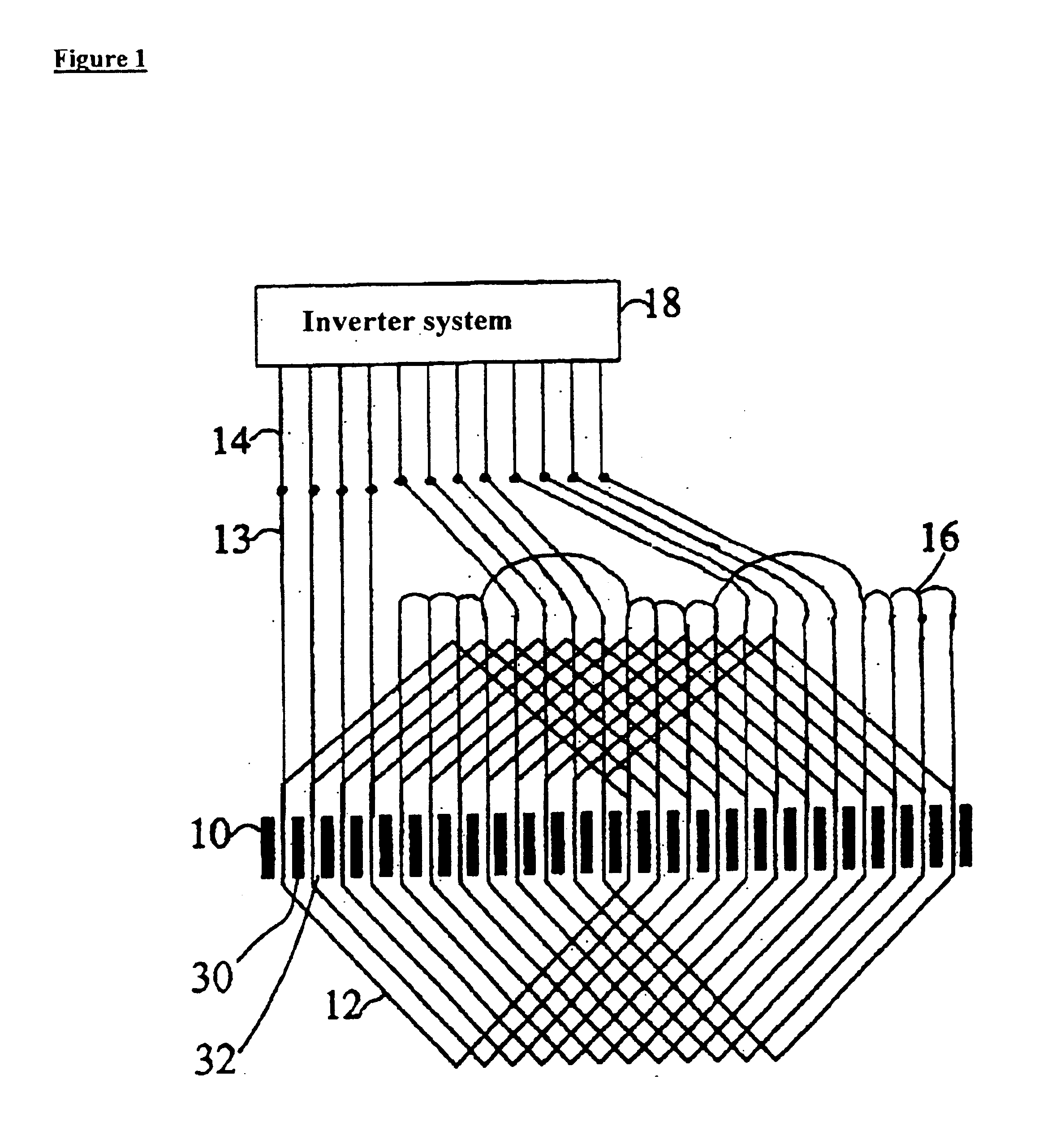
[0054]FIG. 1 illustrates a schematic of the windings of an induction apparatus of the present invention. FIG. 1 depicts a stator 10 and inverter system 18. Inverter system 18, depicted in FIG. 1, uses half bridge inverters, however, the present invention may utilize either half or full bridge inverters. Stator 10 includes stator teeth 30 and slots 32. Coils 12 pass through slots 32.

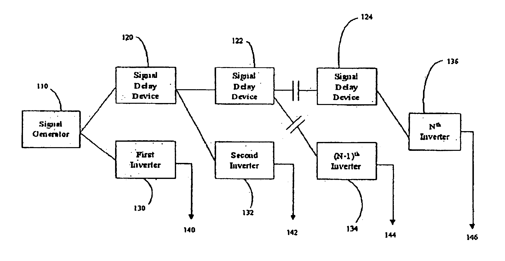
[0055]Inverter system 18 is comprised of a plurality of inverters, such that the ...


PUM


Abstract

An electrical rotating apparatus comprises an inverter system that outputs more than three phases. The apparatus further includes a stator electrically coupled to the inverter system, and a rotor electromagnetically coupled to a magnetic field generated by the stator. A signal generator generates a pulse modulated drive waveform signal, that has a frequency synchronized with the rotational frequency of the rotor, and the pulse modulated drive waveform signal drives the inverter system. The pulse modulated drive waveform signal has a pulsing frequency. Additionally, the inverter system may be fed by a pulse modulated drive waveform signal that is fed through at least one signal delay device. Alternatively, the system may also be fed selected harmonic components, such as the third harmonic, up until the number of phases in the apparatus.

Description

CROSS-REFERENCE TO RELATED APPLICATIONS[0001]This application claims the benefit of U.S. Provisional Application Nos. 60 / 360,157 and 60 / 360,215, both filed 25 Feb. 2002. This is a continuation-in-part of application Ser. No. 09 / 255,291, filed 22 Feb. 1999 now U.S. Pat. No. 6,570,361. This application is related to application Ser. No. 09 / 713,654, filed 15 Nov. 2000, now U.S. Pat. No. 6,657,334, which claims the benefit of U.S. Provisional Application No. 60 / 242,622, filed 23 Oct. 2000. This application is al so related to application Ser. No. 08 / 715,482, filed 18 Sep. 1996, now U.S. Pat. No. 6,054,837, which is a continuation-in-part of application Ser. No. 08 / 350,737, filed 7 Dec. 1994, and now abandoned, which is a continuation-in-part of application Ser. No. 08 / 267,043, filed 28 Jun. 1994, and now abandoned.BACKGROUND OF THE INVENTION[0002]This invention relates generally to rotating induction apparatus and more specifically to more efficient rotating induction apparatus. It rela...

Claims


Application Information

Patent Timeline
Patent Type & Authority Patents(United States)
IPC IPC(8): H02K3/28H02P29/00H02M7/505H02M7/521H02K29/03
CPCH02K3/28H02M7/521H02P29/0038H02K29/03Y10S388/921H02P29/50
Inventor EDELSON, JONATHAN SIDNEY
Owner BOREALIS TECH LTD
Why Eureka
Try Eureka