
Apparatus for and method of measuring jitter

a technology of jitter and apparatus, applied in the field of apparatus for and a method of measuring period jitter, can solve the problems of overestimation of jitter values, inability to accurately estimate the histogram of jitter, and long time required to acquire a number of data, and achieve the effect of measuring more accurately

Inactive Publication Date: 2005-07-26
ADVANTEST CORP
View PDF4 Cites 41 Cited by
  • Summary
  • Abstract
  • Description
  • Claims
  • Application Information

AI Technical Summary

Benefits of technology

The present invention provides a method for accurately measuring the timing of a signal under measurement by sampling the signal at a close proximity to the zero-crossing points of the signal. This method uses a correction term to account for the deviation of the zero-crossing points from their ideal positions, resulting in a more accurate measurement of the period jitter of the signal. The correction term is obtained by multiplying the ratio of the fundamental period of the signal to the time interval between the zero-crossing points. This method can be used to measure the phase noise of a signal and the timing of a signal under measurement with high accuracy.

Problems solved by technology

However, because this method repeatedly measures jitter but includes an intermediate dead-time between measurements, there is a problem that it takes a long time to acquire a number of data that are required for a histogram analysis.
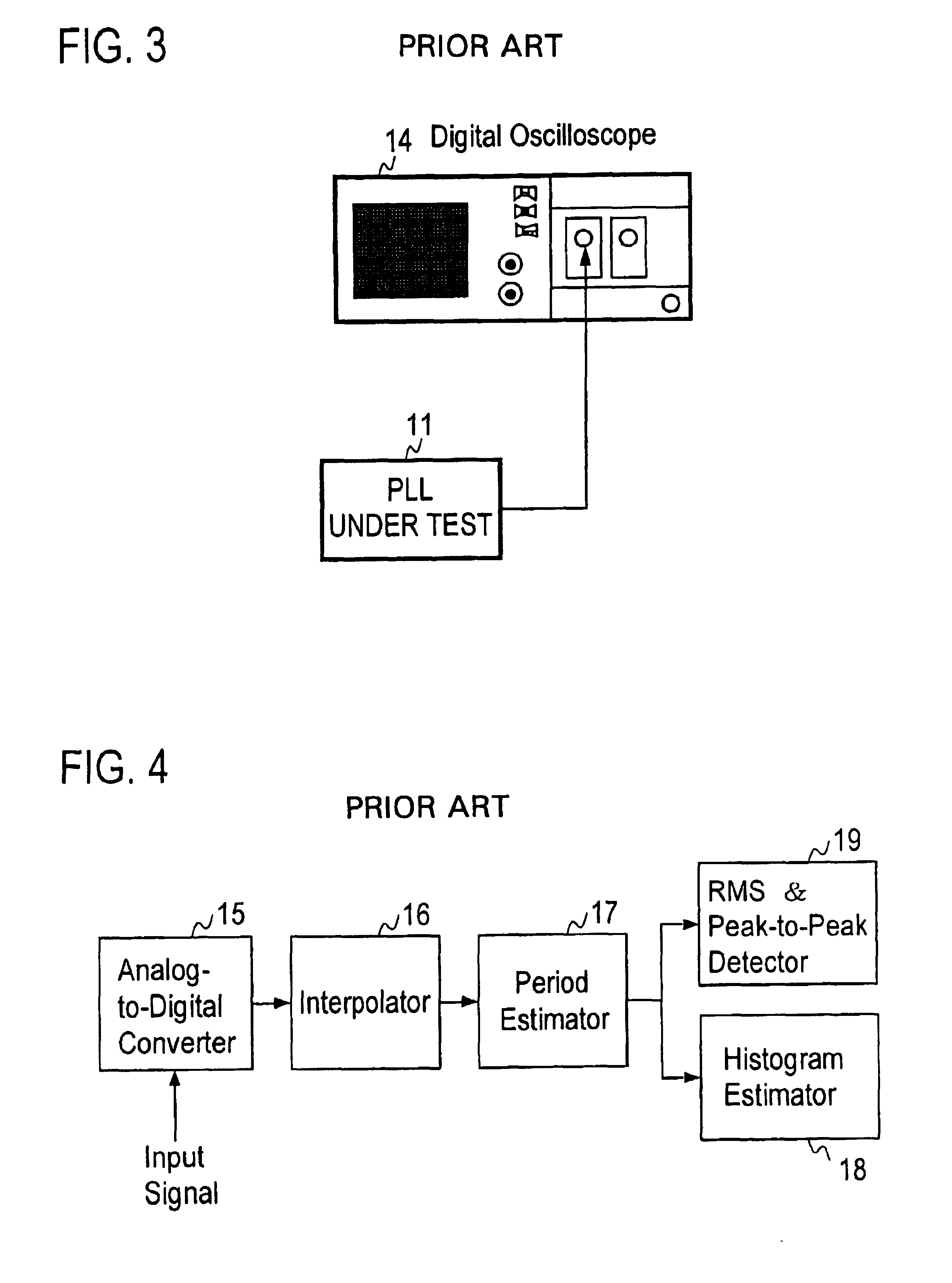
In addition, in an interpolation-based jitter measurement method in which a wide-band oscilloscope and an interpolation method are combined, there is a problem that a histogram of jitter cannot accurately be estimated, and a jitter values are overestimated (overestimation).

Method used


Image

  • Apparatus for and method of measuring jitter
  • Apparatus for and method of measuring jitter
  • Apparatus for and method of measuring jitter

Examples


Embodiment Construction

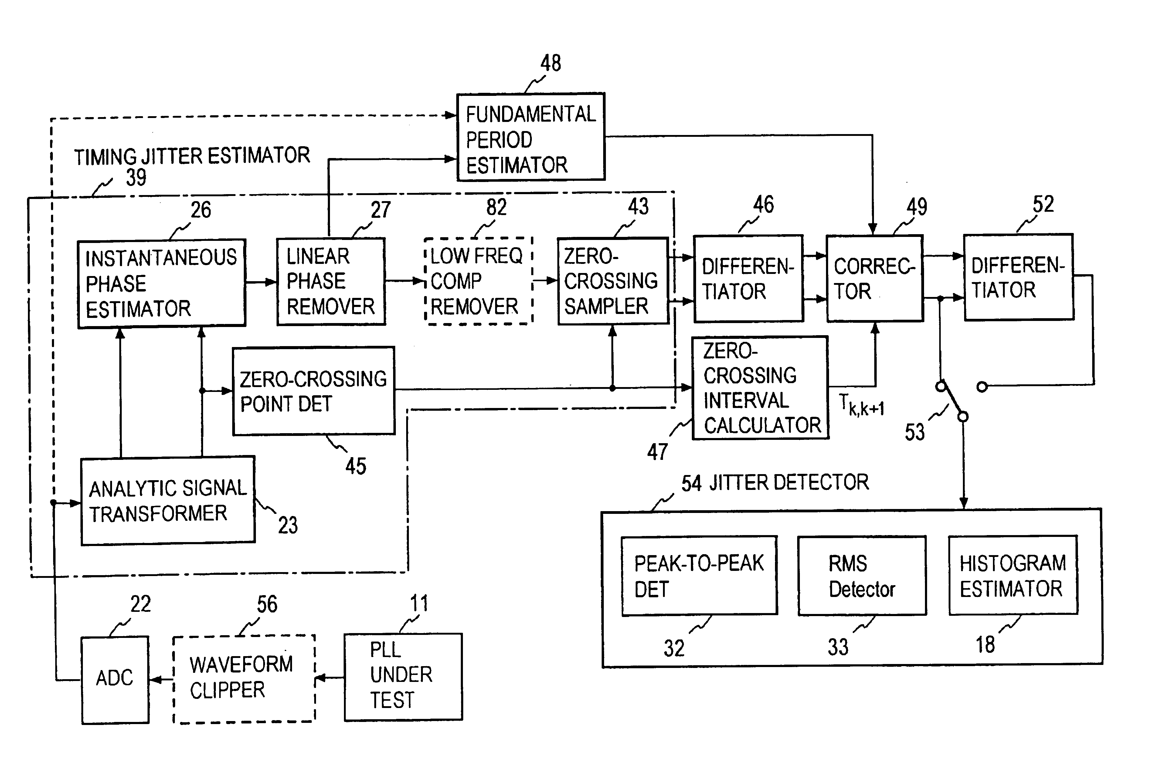
[0045]FIG. 12 shows an embodiment of the present invention. Portions in FIG. 12 corresponding to those in FIG. 6 have the same reference numbers affixed thereto as those in FIG. 6, and duplicated explanations for those portions will be omitted. According to the present invention, a signal under measurement xc(t) is inputted to a timing jitter estimator 39, and a timing jitter sequence of the inputted signal under measurement is obtained. In this embodiment, an instantaneous phase noise waveform Δφ(t) obtained from a linear phase remover 27 is sampled by a zero-crossing sampler 43 at timings closest to zero-crossing points of a real part xc(t) of an analytic signal zc(t) to obtain a timing jitter sequence. For this reason, a real part xc(t) of an analytic signal from an analytic signal transforming part 23 is inputted to a zero-crossing point detecting part 45.

[0046]Next, approximated zero-crossing points are detected by the zero-crossing point detecting part 45. That is, the maximum...


PUM


Abstract

A signal under measurement x(t) is transformed into a complex analytic signal zc(t), and an instantaneous phase of the xc(t) is estimated using the zc(t). A linear phase is removed from the instantaneous phase to obtain a phase noise waveform Δφ(t) of the x(t), and the Δφ(t) is sampled at a timing close to a zero-crossing timing of the x(t) to obtain a timing jitter sequence. Then a difference sequence of the timing jitter sequence is calculated to obtain a period jitter sequence. The period jitter sequence is multiplied by a ratio T0 / Tk,k+1 of the fundamental period T0 of the x(t) and the sampling time interval Tk,k+1 to make a correction of the period jitter sequence. A period jitter value of the x(t) is obtained from the corrected period jitter sequence.

Description

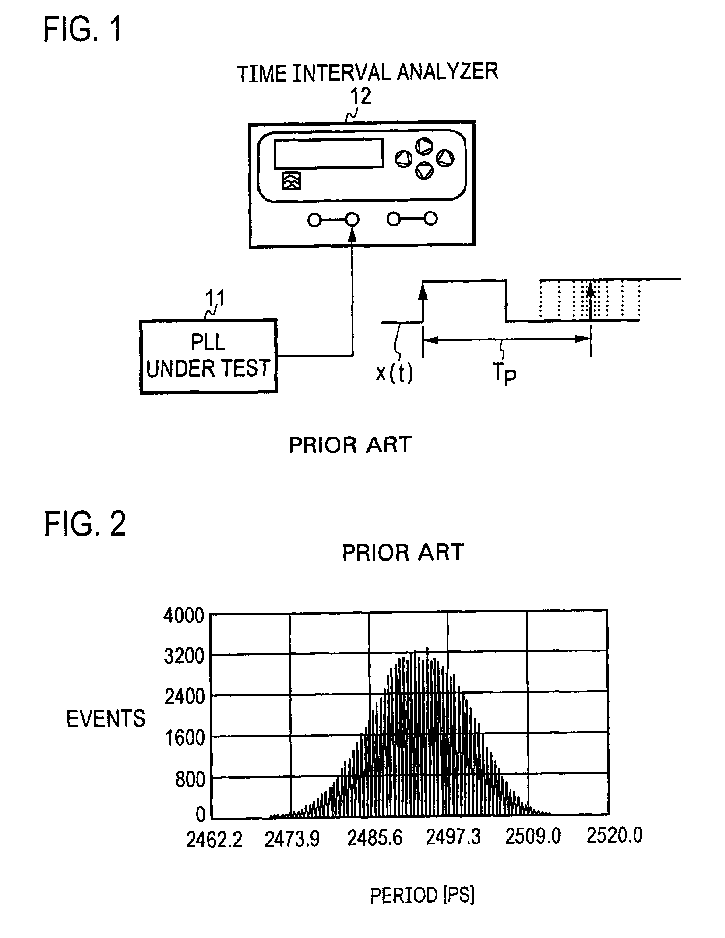
BACKGROUND OF THE INVENTION[0001]The present invention relates to an apparatus for and a method of measuring period jitter that are applied to a measurement of jitter of, for example, a microprocessor clock.[0002]A time interval analyzer and / or an oscilloscope have conventionally been used for the measurement of period jitter. The method of these apparatus is called Zero-crossing Method, in which, as shown in FIG. 1, a clock signal (a signal under measurement) x(t) from, for example, a PLL (Phase-Locked Loop) under test 11 is supplied to a time interval analyzer 12. Regarding a signal under measurement x(t), a next rising edge following one rising edge fluctuates against the preceding rising edge as indicated by dotted lines. That is, a time interval Tp between the two rising edges, namely a period fluctuates. In the Zero-crossing Method, a time interval between zero-crossings (period) of the signal under measurement is measured, a fluctuation of period is measured by a histogram an...

Claims


Application Information

Patent Timeline
Patent Type & Authority Patents(United States)
IPC IPC(8): G01R29/26G01R29/02G01R29/00G01R29/027H04L1/20H03K5/26
CPCG01R29/0273G01R29/26H04L1/205
Inventor YAMAGUCHI, TAKAHIROISHIDA, MASAHIROSOMA, MANI
Owner ADVANTEST CORP
Learn More