Eureka AIR delivers breakthrough ideas for toughest innovation challenges, trusted by R&D personnel around the world.

System and method of pumping liquified gas

a technology of liquid gas and pumping station, which is applied in the direction of positive displacement liquid engine, container discharging method, liquid fuel engine, etc., can solve the problems of increasing the difficulty of pumping station, affecting the ability to pump, so as to reduce the cost of pumping station and the cost of installation

Inactive Publication Date: 2005-08-02
MICHAEL D HOLT COMPANY
View PDF16 Cites 15 Cited by
  • Summary
  • Abstract
  • Description
  • Claims
  • Application Information

AI Technical Summary

Benefits of technology

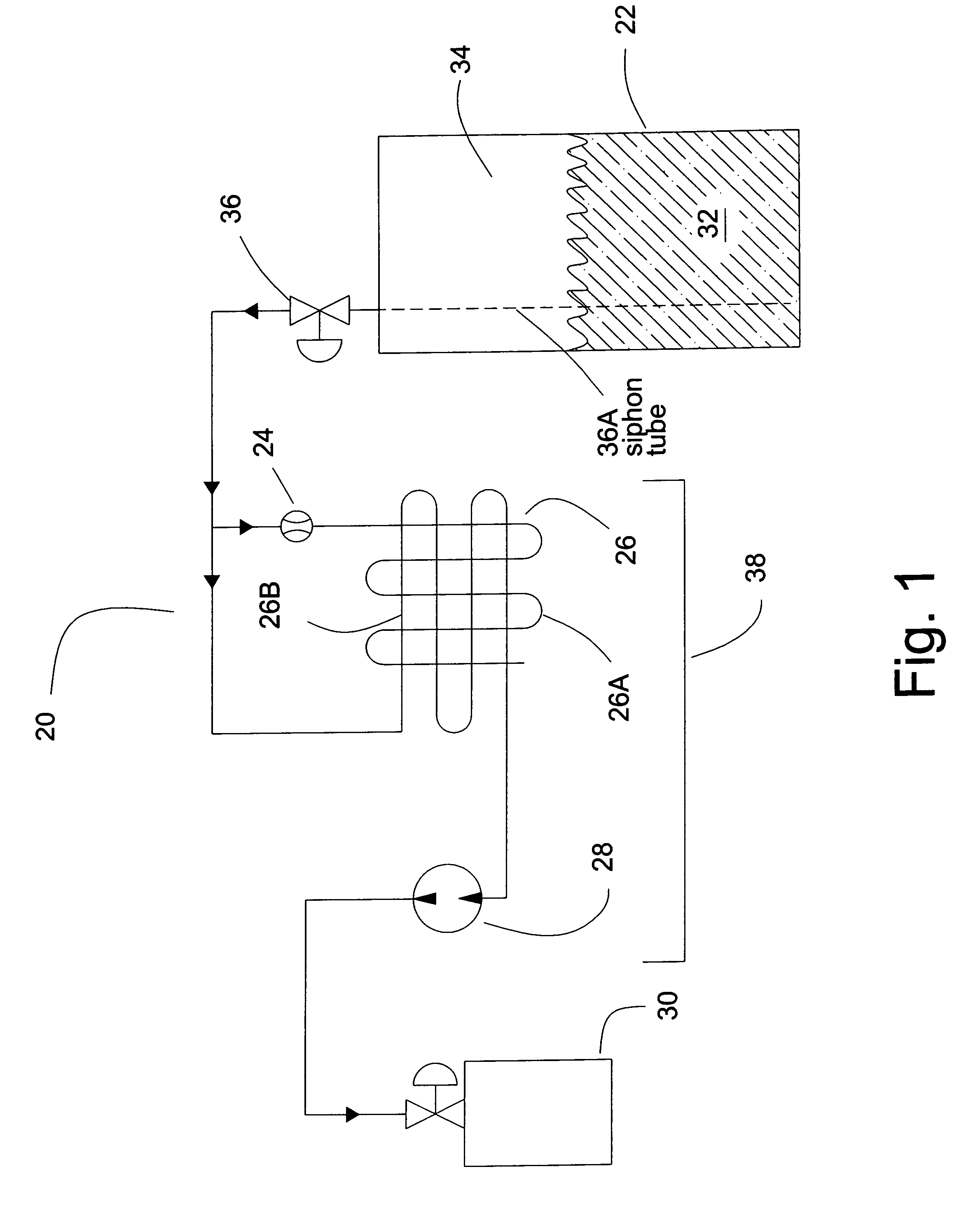
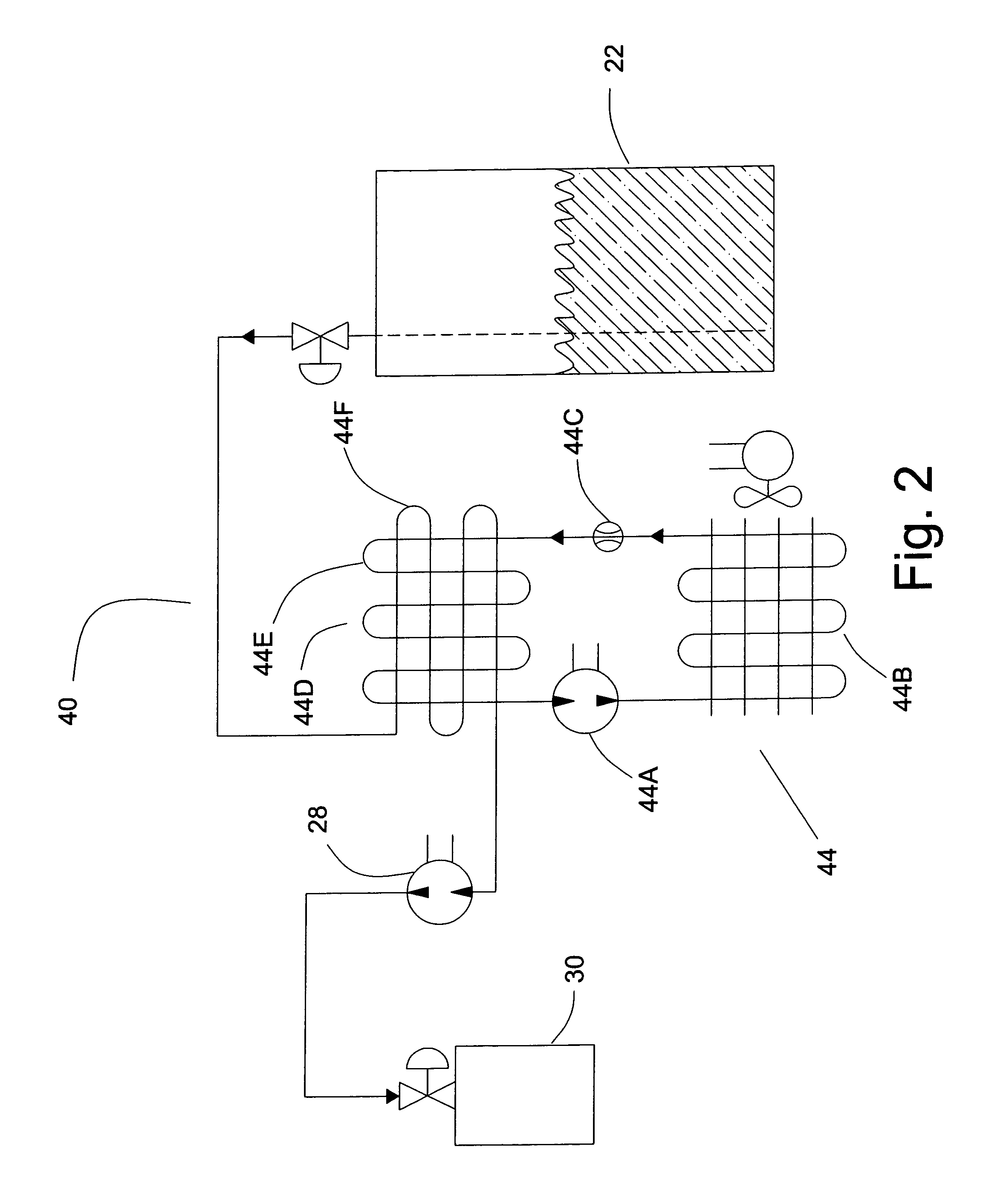
[0003]Historically it has been the function of industrial gas fill plants to convert, or pump, the low pressure refrigerated liquefied gases into the non-refrigerated higher pressure vessels. These pumping stations are expensive to install and usually require the liquefied gas storage vessel to have an outlet port at the bottom of the vessel as well as a recirculation system to prevent vapor locking the pump (vaporizing the gas in the pump). Applicants system and process allows for the use of smaller refrigerated pressure vessels which have connections on the top of the pressure vessels and eliminates the need for a recirculating system, significantly reducing the cost of the pumping station.
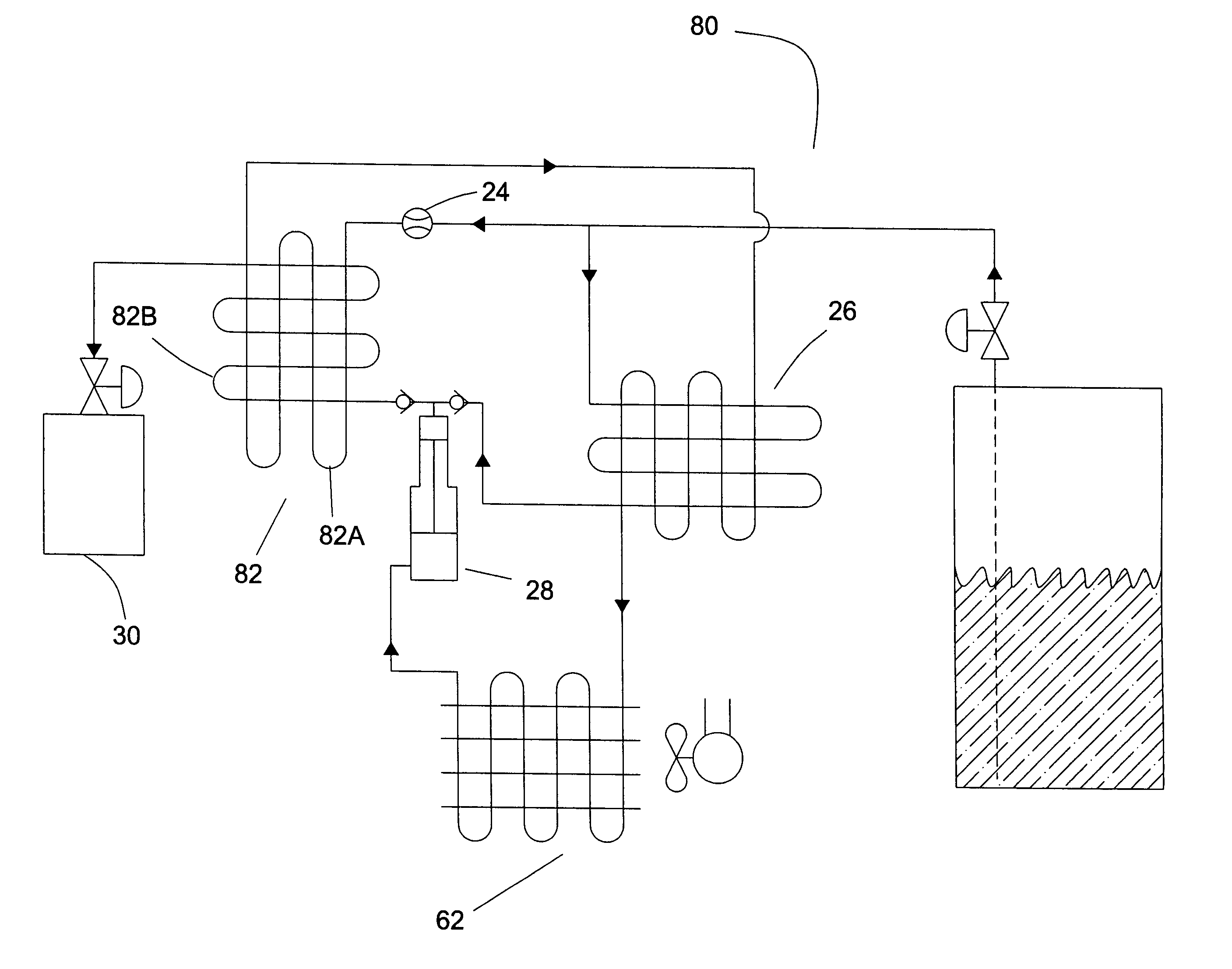
[0005]Applicant's present invention makes use of a heat exchanger to sub cool the liquefied gas below its equilibrium point, stabilizing the liquid, preventing it from vaporizing as it is subjected to the pressure reduction and temperature increase on the suction side of the pump.

Problems solved by technology

These pumping stations are expensive to install and usually require the liquefied gas storage vessel to have an outlet port at the bottom of the vessel as well as a recirculation system to prevent vapor locking the pump (vaporizing the gas in the pump).
This vaporization impairs the ability to be able to “pump” the liquified gas.
It becomes increasingly difficult to pump liquified gases from portable refrigerated storage vessels (Dewars) using conventional pumping setups as the connections for the Dewars is through the top and the liquid is withdrawn by means of as dip tube, or siphon tube which extends into the liquid at the bottom of the vessel.
Extracting liquified gas from the Dewars up through the dip tube results in a slight loss of pressure.
Compounding the inability to gravity feed the liquid is the difficulty in establishing any type of recirculating system using a Dewar, because standardized Dewars do not have a suitable port for a return line into the bottom of the vessel.
The inability of establishing recirculating systems in Dewars previously has resulted in the pumps being warmer than the temperature of the liquified gas in the storage vessel, increasing the potential for vapor lock at the pump.
Consequently the use of the Dewar cylinders has been restricted to a high volume end users, or use with expensive high volume pumps, and the conversion of low pressure liquefied gases into high pressure non-refrigerated cylinders is generally left to large scale industrial gas pumping stations.

Method used


Image

  • System and method of pumping liquified gas
  • System and method of pumping liquified gas
  • System and method of pumping liquified gas

Examples


Embodiment Construction

[0011]Chart 1 is a simplified temperature-pressure chart for Carbon Dioxide (CO2). This chart graphs the equilibrium point between the boiling point (2) at 0 psig and −109.3° F. and the critical point (4) at 1056 psig and 87.9° F. The critical point is the point after which all liquid vaporizes without regard to pressure.

[0012]Often commercially available refrigerated CO2 is stored at around 0° F. (6) resulting in a pressure of about 290 psig. Conventionally the industrial gas fill plants have pumped, or increased the pressure of this refrigerated liquefied CO2 as it went into non-refrigerated cylinders at say 70° F., which results in a pressure increase of about 550 psig. When pumping care must be taken to ensure the liquid is not subjected to lower pressure (8) or higher temperatures (10) as this will cause the gas to vaporize, impeding the pumping process.

[0013]Applicants process and system makes use of a heat exchanger to subcool the liquid between the storage vessel and the pum...


PUM


Abstract

A system and method of pumping liquified gas. Applicants systems includes a liquified gas storage vessel and a smaller high pressure high pressure liquified gas storage cylinder. Applicant provides a pump between the two vessels for pumping the liquified gas from one vessel to the other. Applicants system also includes at least one heat exchanger through which the liquified gas passes as it is pumped from one vessel to the other, which heat exchanger cools the liquified gas that is being pumped to a temperature typically below the vaporization point of the gas.

Description

FIELD OF INVENTION[0001]Pumping systems, more specifically pumping method and devices for the movement of liquified gas into a high pressure cylinder.BACKGROUND[0002]In the compressed gas industry, there are two basic types of pressure vessels used to contain the gases; refrigerated and non-refrigerated. In the non-refrigerated storage vessels the gases are stored at atmospheric temperatures and they are generally kept at higher pressure than in the refrigerated vessels. Nearly all bulk gas is produced, transported, and stored in a refrigerated state. The actual temperatures that the gases are stored at varies by the type of gas, and can range from 0° F. to −350° F., but the principal of refrigerating a gas to maintain it as a low pressure liquid is similar with many types of gas. The benefits of keeping gasses as refrigerated liquids include more condensed storage and handling and lower pressure.BRIEF DESCRIPTION OF THE INVENTION[0003]Historically it has been the function of indust...

Claims


Application Information

Patent Timeline
IPC IPC(8): F17C13/00F17C5/00
CPCF17C5/00F17C2225/0153F17C2227/0135F17C2227/0157F17C2227/0337F17C2227/0393F17C2250/0636F17C2265/06F17C2270/05F17C2201/0104F17C2205/0338F17C2205/035F17C2221/011F17C2221/013F17C2221/014F17C2223/0153F17C2223/042
Inventor MARKHAM, TREVOR K.ARNOTT, GLEN M.
Owner MICHAEL D HOLT COMPANY
Why Eureka
Eureka Blog
Learn More