Drill having construction for reducing thrust load in drilling operation, and method of manufacturing the drill

a drilling operation and construction technology, applied in the field of drilling, can solve the problems of undesirable reduction of rigidity or mechanical strength of the drill, difficult to reduce the thrust load applied, and inability to provide satisfactorily prolonged tool life, etc., to achieve the effect of reducing the thickness of the web, prolonging the tool life, and reducing the thirst load applied

Inactive Publication Date: 2005-08-02
OSG
View PDF42 Cites 41 Cited by
  • Summary
  • Abstract
  • Description
  • Claims
  • Application Information

AI Technical Summary

Benefits of technology

[0009]The present invention was made in view of the background prior art discussed above. It is therefore a first object of the present invention to provide a drill having a tool life prolonged owing to its construction which is effective to reduce a thirst load applied to the drill during a drilling operation for a hole, without reducing a web thickness over the entire length of the drill body, and which is also effective to reduce a generation of friction heat, a wear of the drill and a cutting torque that are caused or increased by frictional contact of margins of the drill and an inner circumferential surface of the hole during the drilling operation. This first object may be achieved according to any one of first through fifteenth aspects of the invention which are described below.

Problems solved by technology

The step 122 impedes the evacuation of the chips, making it difficult to reduce a thrust load applied to the drill during a drilling operation, thereby making it impossible to provide a satisfactorily prolonged tool life.
However, a considerable reduction in the web thickness over the entire length of the drill body leads to an undesirable reduction in the rigidity or mechanical strength of the drill, failing to provide a technical advantage favorable for an increase in the tool life after all.
Further, the above-described conventional drill suffers from other problems that a cutting torque is undesirably increased due to a friction generated by contact of margins of the drill with an inner circumferential surface of the hole, thereby deteriorating a cutting performance of the drill, and that a friction heat and a wear of each of the margins are generated and caused by the contact of the margins and the inner circumferential surface of the hole, thereby reducing the tool life, i.e., the number of the holes which can be drilled without regrinding or resharpening the cutting edges of the drill.
However, a considerable reduction in the margin width leads to a reduction in the strength of each margin, probably causing fracture at a boundary between the margin and the flank surface of a land (which is located on the rear side of the margin), and the consequent chipping of a leading edge (which is provided by the rear-side one of widthwise opposite edges of the chip evacuation flute).

Method used


Image

  • Drill having construction for reducing thrust load in drilling operation, and method of manufacturing the drill
  • Drill having construction for reducing thrust load in drilling operation, and method of manufacturing the drill
  • Drill having construction for reducing thrust load in drilling operation, and method of manufacturing the drill

Examples


Embodiment Construction

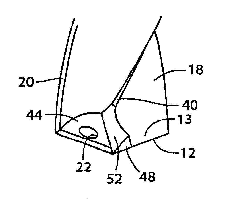
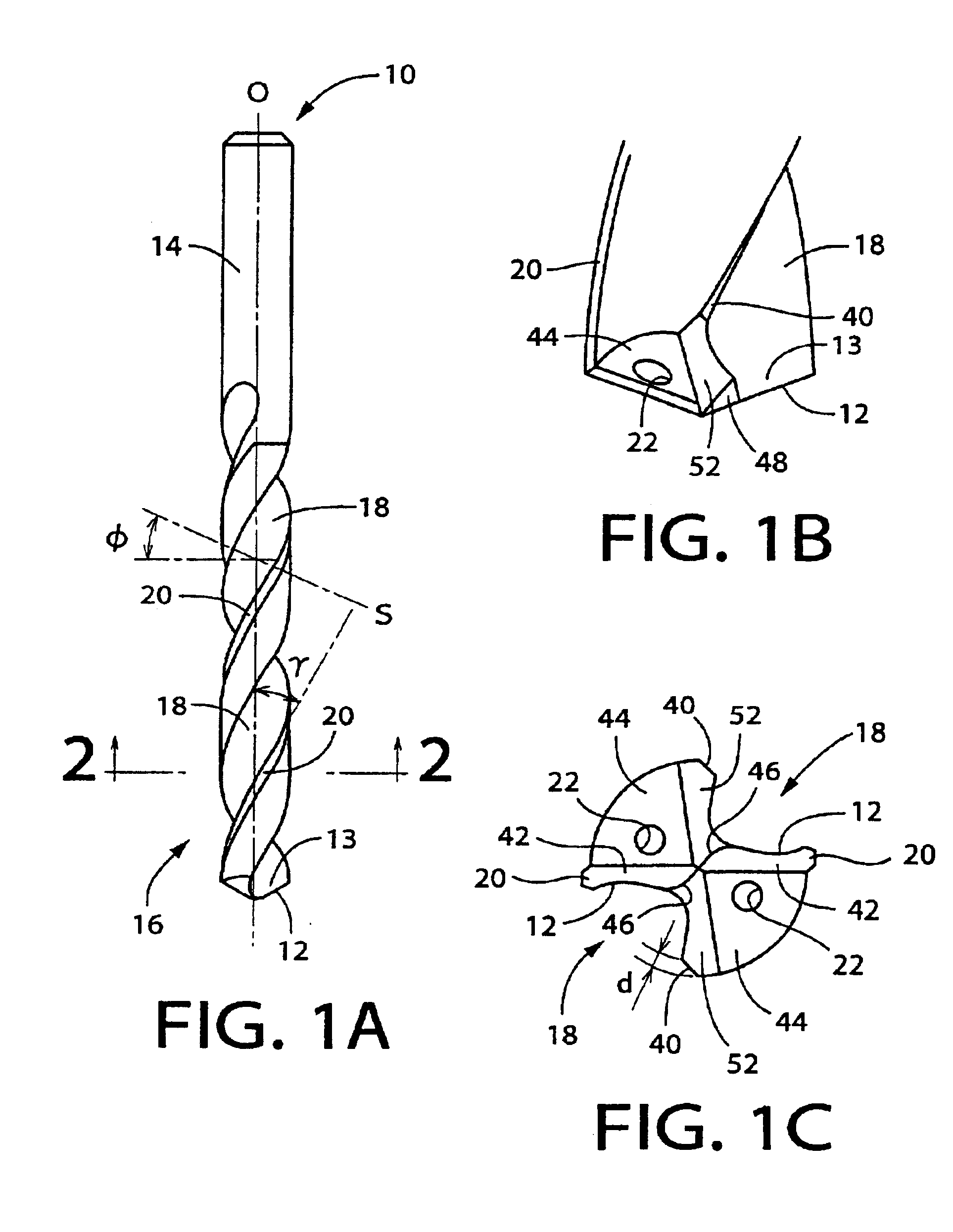
[0080]FIGS. 1A-1C show a drill 10 which is constructed according to an embodiment of this invention. FIG. 1A is a front elevational view of the drill 10 as seen in a direction perpendicular to an axis O of the drill 10. FIG. 1B is a front view showing in enlargement an axially distal end portion of the drill 10 in which a pair of cutting lips or edges 12 and their respective rake surfaces 13 are formed. FIG. 1C is a lower plan view of the drill 10, showing in enlargement the axially distal end portion of the drill 10. This drill 10 is of a two-fluted twist drill, and is formed of a cemented carbide. The drill 10 includes a cylindrical shank portion 14 and a cylindrical body portion 16 which are coaxial with each other and which are formed integrally with each other. The integrally formed cylindrical shank and body portions 14, 16 cooperate with each other to constitute a body of the drill 10, which is referred to as a drill body. The cylindrical body portion 16 has a pair of chip ev...


PUM

PropertyMeasurementUnit
angleaaaaaaaaaa
clearance angleaaaaaaaaaa
angle α1aaaaaaaaaa

Abstract

A drill including a shank portion and a cylindrical body portion contiguous to each other. The cylindrical body portion includes (a) primary cutting edges and secondary cutting edges formed in its axially distal end portion such that each of the secondary cutting edges is located on a radially inner side of the corresponding primary cutting edge; (b) primary rake surfaces of the primary cutting edges and secondary rake surfaces of the secondary cutting edges; and (c) inclined surfaces each of which extends from the corresponding secondary rake surface to a periphery of the cylindrical body portion, and is inclined such that an axial distance between each of the inclined surfaces and the shank portion is reduced as viewed in a direction substantially perpendicular to the corresponding secondary cutting edge, from the corresponding secondary rake surface toward the periphery of the cylindrical body portion. Each of the secondary rake surfaces and the corresponding secondary cutting edge are formed together with each other in a web thinning. Each of the secondary rake surfaces and the corresponding inclined surface are connected to each other without a step therebetween.

Description

BACKGROUND OF THE INVENTION[0001]1. Field of the Invention[0002]The present invention relates in general to a drill, and more particularly to techniques for providing a drill with a long tool life, by reducing a thrust load applied to the drill during a drilling operation for drilling a hole, and also by reducing a generation of friction heat, a wear of the drill and a cutting torque which are caused or increased by frictional contact of margins of the drill and an inner surface of the hole during the drilling operation.[0003]2. Discussion of the Related Art[0004]There is widely known a drill which has cutting lips or edges formed in its axially distal end portion, and chip evacuation flutes formed to extend generally in its axial direction. The drill is used to originate or enlarge a hole in a workpiece, by rotating the drill about its axis and moving the drill and the workpiece relative to each other in the axial direction, so that the workpiece is cut with the cutting edges while...

Claims


Application Information

Patent Timeline
Patent Type & Authority Patents(United States)
IPC IPC(8): B23B51/02B23B51/00
CPCB23B51/02B23B2250/12Y10T408/9097B23B2251/44B23B2251/14
Inventor OSAWA, JIROKOBAYASHI, KENJIROKASUYA, KAZUHISAYAMAMOTO, TAKAHIROTAKIKAWA, YOSHIHIRO
Owner OSG
Why Eureka
Try Eureka