Heat controlled ultraviolet light apparatus and methods of sanitizing objects using said apparatus

Inactive Publication Date: 2005-08-02
BRICKLEY JAMES LAWRENCE
View PDF30 Cites 23 Cited by
  • Summary
  • Abstract
  • Description
  • Claims
  • Application Information

AI Technical Summary

Benefits of technology

[0011]More specifically, the apparatus of the present invention includes a heating or cooling element that may be selectively controlled to provide the necessary amount of heating/cooling to maintain the ultraviolet light source at a desired temperature range thereby maximizing the efficiency of the UV light source in producing ultraviolet light. Preferably, the ultraviolet light source of the present invention can be categorized as a “hot UV” lamp, and more particularly, a low pressure mercury lamp that is most efficient in producing ultraviolet light when the lamp is maintained at a temperature between about 80-90° F. A heat sensor, such as a thermocouple or any other type of sensor, may be placed adjacent the ultraviolet light sou

Problems solved by technology

One disadvantage with mercury lamps is that they are unable to adequately function in temperatures that fall outside optimal operating temperatures of the mercury lamps.
UV light sources have been proven to be effective in sanitizing and disinfect

Method used


Image

  • Heat controlled ultraviolet light apparatus and methods of sanitizing objects using said apparatus
  • Heat controlled ultraviolet light apparatus and methods of sanitizing objects using said apparatus
  • Heat controlled ultraviolet light apparatus and methods of sanitizing objects using said apparatus

Examples


Example

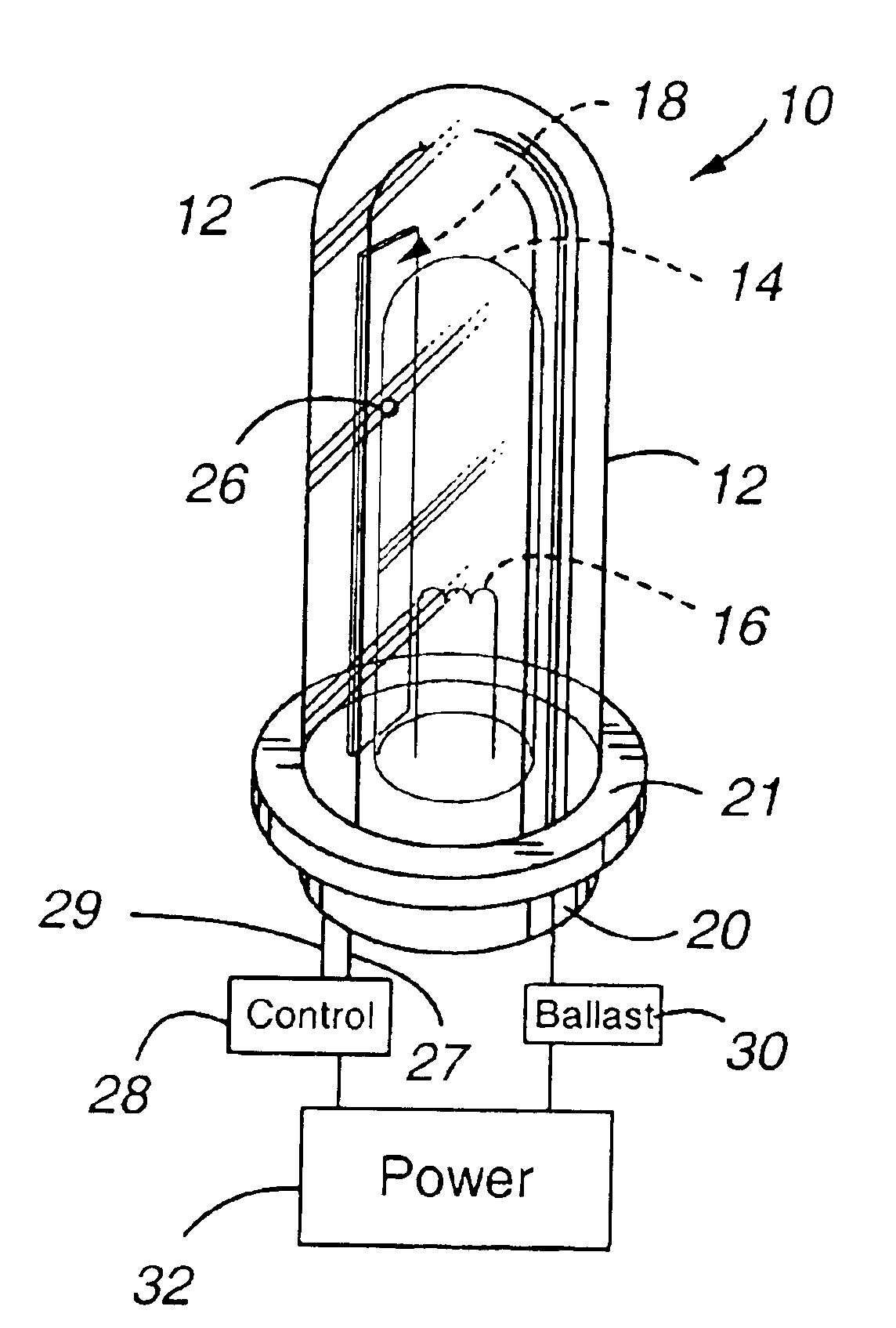
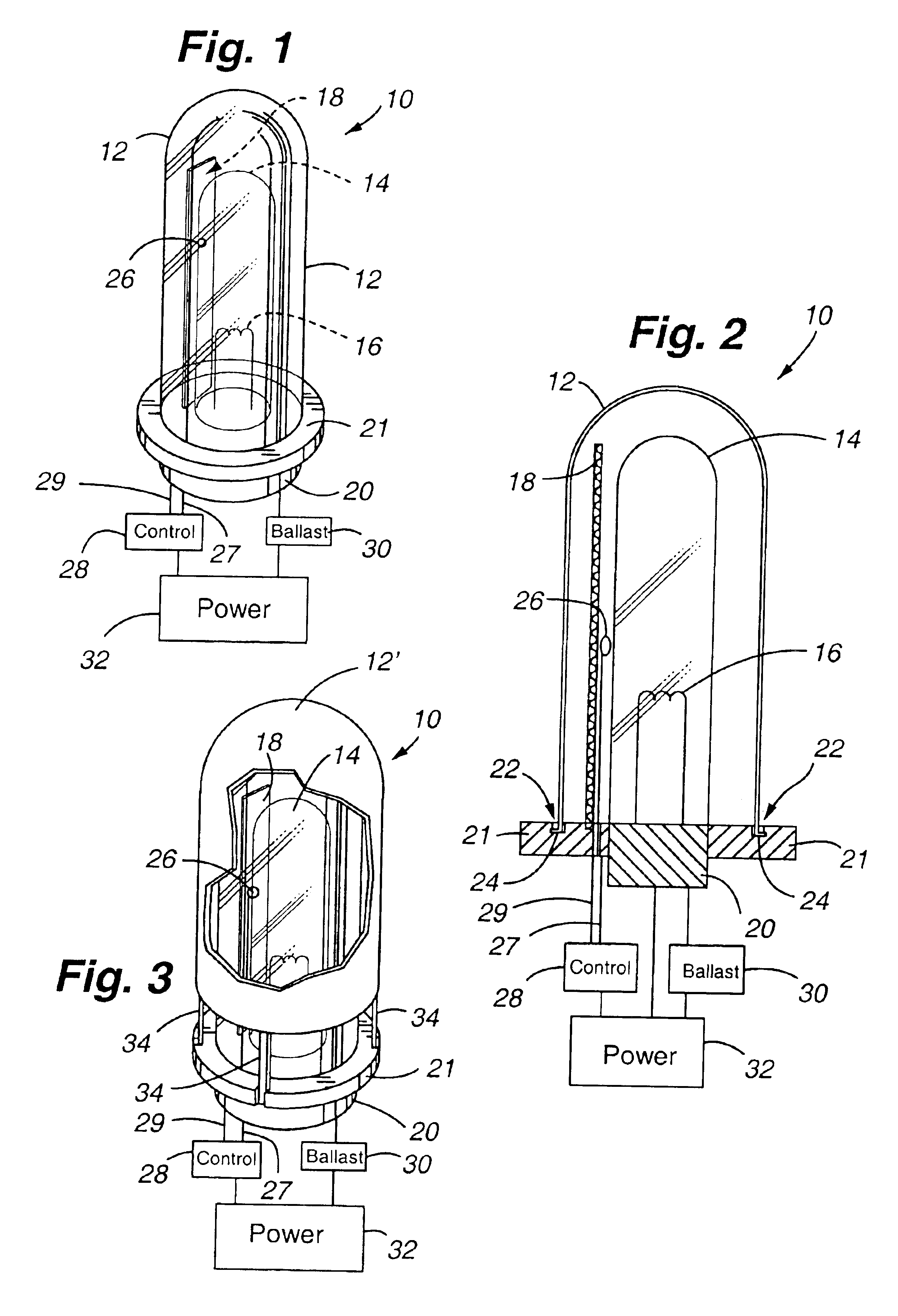
[0024]Referring first to FIG. 1, the heat controlled ultraviolet light apparatus 10 of the present invention is shown. The apparatus includes a UV transmissive cover 12, an ultraviolet lamp or bulb 14, and a heating / cooling element 18 that is placed in the gap or space between the bulb 14 and the cover 12. The particular type of ultraviolet bulb or lamp 14 shown includes one with a filament 16 which is used to excite a metal such as mercury housed in the lamp. One or more rare gases additionally fill the interior of the bulb so that a plasma field can be created, thus generating both visible and ultraviolet light. Although a particular type of ultraviolet lamp is shown, it shall be understood that the present invention can utilize any type of ultraviolet lamp. The bulb 14 may include an integral bulb base 20, which is most common in ultraviolet lamp constructions. As required, the bulb base may further include an internal ballast incorporated with base 20, or an external ballast 30 ...


PUM


Abstract

A heat controlled ultraviolet light apparatus includes a source of ultraviolet light, a cover, and a heating or cooling element that heats/cools the space or gap between the ultraviolet light source and the cover. Accordingly, the ultraviolet light source may be maintained at an optimal temperature thereby maximizing the efficiency of the ultraviolet light source in producing ultraviolet radiation. The apparatus may further include a temperature sensor and a control circuit to automatically control production of heat/cooling by the element based upon the ambient temperatures experienced by the ultraviolet light source during use. Methods are also provided for sanitizing heating and cooling coils of various devices such as an HVAC system, and cooling systems such as a refrigeration unit and an evaporative cooler.

Description

TECHNICAL FIELD[0001]The present invention relates generally to methods and apparatuses for disinfecting objects utilizing an ultraviolet light source, and more particularly, to an ultraviolet light source that is maintained at a desired temperature range by heating or cooling, as necessary, thereby maximizing the efficiency of the ultraviolet light source in producing ultraviolet rays.BACKGROUND OF THE INVENTION[0002]An ultraviolet light source is a well known means for sanitizing and disinfecting many targeted objects to include fluids. When administered at the desired frequencies, durations, and intensities, ultraviolet (UV) light is able to kill a wide array of micro-organisms that include, but not limited to, bacteria, viruses, spores, algae and protozoa, without having to chemically treat the object to be disinfected. One type of common UV bulb includes a quartz or glass casing that holds a vaporizable material, such as mercury, and also holds a stabilizing gas. The stabilizin...

Claims


Application Information

Patent Timeline
IPC IPC(8): A61L2/10F25D17/04F24F3/16H01J61/34H01J61/52
CPCA61L2/10F24F3/166F25D17/042H01J61/34H01J61/52F24F2003/1667F24F2221/22F25D2317/0417F24F8/192F24F8/22Y02A50/20
Inventor BRICKLEY, JAMES LAWRENCE
Owner BRICKLEY JAMES LAWRENCE
Why Eureka
Try Eureka