Brushless motor drive device

a brushless dc motor and drive device technology, applied in the direction of motor/generator/converter stopper, electronic commutator, dynamo-electric converter control, etc., can solve the problem of thermal shutdown mechanism, and achieve the effect of preventing the frequency of pulse signal

US6924611B1Active Publication Date: 2005-08-02GLOBAL MIXED MODE TECH
6 Cites 39 Cited by

Patent Information

Authority / Receiving Office
US · United States
Patent Type
Patents(United States)
Current Assignee / Owner
Publication Date
2005-08-02

Smart Images

  • Figure 1
    Figure 1
  • Figure 2
    Figure 2
  • Figure 3
    Figure 3
Patent Text Reader

Abstract

A Hall sensing circuit generates a positional detection signal representative of a positional relationship between a rotor and a phase coil of a motor. A signal synthesizing circuit transforms the positional detection signal to a driving signal. Based on a comparison of the driving signal and a high-frequency reference signal, a pulse signal is generated for controlling a switching circuit to dive the motor. A current error signal is supplied through feedback to adjust a relative relationship between an amplitude of the drive signal and an amplitude of the high-frequency reference signal, thereby changing a duty ratio of the pulse signal. A duty-ratio limiting circuit is provided to limit the duty ratio of the pulse signal for ensuring a reliable rotation of the motor.
Need to check novelty before this filing date? Find Prior Art

Description

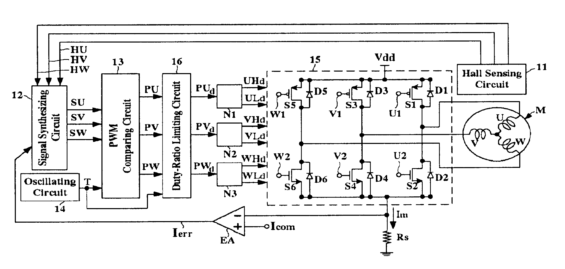
BACKGROUND OF THE INVENTION

[0001] 1. Field of the Invention

[0002] The present invention relates to a motor drive device and, more particularly, to a motor drive device for a brushless DC motor.

[0003] 2. Description of the Related Art

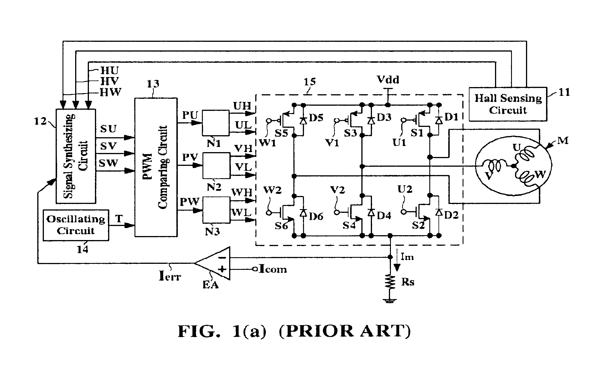
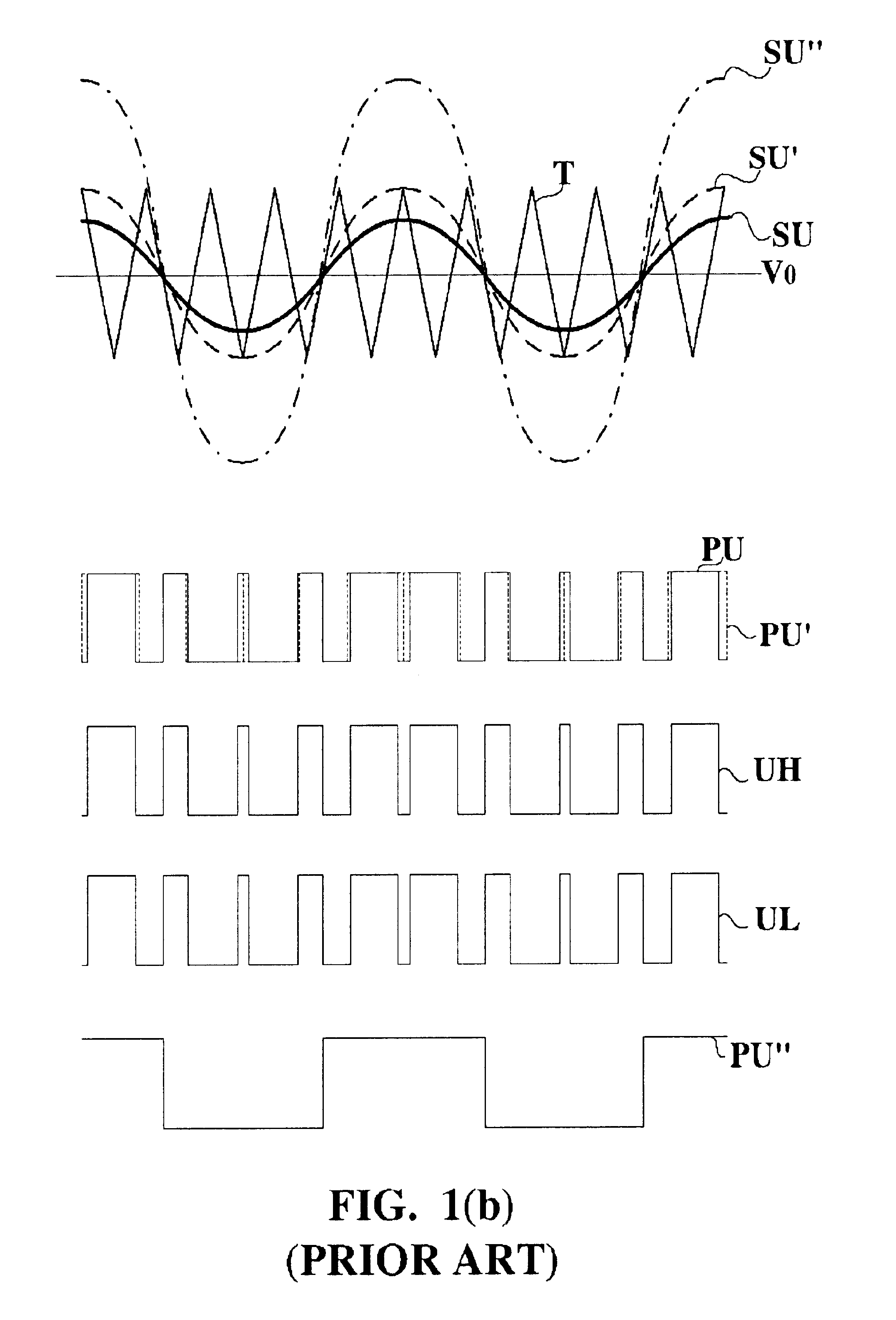
[0004] FIG. 1(a) is a circuit block diagram showing a conventional brushless motor drive device. Referring to FIG. 1(a), a motor M is a three-phase DC brushless motor having three phase coils U, V, and W. A Hall sensing circuit 11 is arranged around the motor M for detecting a position of a rotor of the motor M, thereby generating three positional detection signals HU, HV, and HW. In response to the positional detection signals HU, HV, and HW, a signal synthesizing circuit 12 generates three sinusoidal drive signals SU, SV, and SW. Subsequently, the sinusoidal drive signals SU, SV, and SW are input to a pulse width modulation (PWM) comparing circuit 13 for being individually compared with respect to a high-frequency triangular signal T generated by an oscill...

Examples

Embodiment Construction

[0023]The preferred embodiments according to the present invention will be described in detail with reference to the drawings.

[0024]FIG. 2(a) is a circuit block diagram showing a brushless motor drive device according to the present invention. Referring to FIG. 2(a), a motor M is a three-phase DC brushless motor having three phase coils U, V, and W. A Hall sensing circuit 11 may include three Hall sensors and three Hall amplifiers for the three phase coils U, V, and W, respectively. The Hall sensing circuit 11 is arranged around the motor M for generating three positional detection signals HU, HV, and HW representative of the positional relationships between a rotor of the motor M and the three phase coils U, V, and W, respectively. Each of the positional detection signals HU, HV, and HW is a sinusoidal signal synchronous with the rotation of the motor M and is 120 degrees out of phase with respect to each other. In response to the positional detection signals HU, HV, and HW, a sign...