
Edge accelerated sense amplifier flip-flop with high fanout drive capability

a technology of fanout drive and amplifier, applied in the direction of pulse generator, pulse technique, electrical apparatus, etc., to achieve the effect of high fanout drive capability

Active Publication Date: 2005-08-02
INTEGRATED DEVICE TECH INC
View PDF13 Cites 24 Cited by
  • Summary
  • Abstract
  • Description
  • Claims
  • Application Information

AI Technical Summary

Benefits of technology

[0005]Flip-flop devices according to embodiments of the present invention can provide fast clock-to-Q timing that exploits the pulsed nature of outputs generated by a clocked sense amplifier. These flip-flop devices include an output stage having a pull-up path and a pull-down path therein that are rendered conductive in response to leading edges of pull-up and pull-down control pulses, respectively. This output stage is also configured to provide the flip-flop device with high fanout drive capability that is supported while one of the control pulses is active. Thereafter, the output stage may enter a high impedance state until the next pulse is received. The flip-flop device also includes a clocked sense amplifier at its front end. This clocked sense amplifier receives data (D and DB) from a differential data source. This data is clocked into the sense amplifier on leading edges of a clock signal CLK. The sense amplifier is configured to generate first and second data output signals, which are typically active low signals (e.g., SB= / SET and RB= / RESET). These active low signals may be treated as active low pulses that are reset to inactive high levels on each trailing edge of the clock signal CLK. For example, receipt of a leading edge of the clock signal CLK when D=1 and DB=0 may cause the first “set” output SB to switch low to an active level while the second “reset” output RB remains high at an inactive level. Thereafter, the next trailing edge of the clock signal CLK may cause the first output SB to switch back high to an inactive level. Similarly, receipt of a leading edge of the clock signal CLK when D=0 and DB=1 may cause the second output RB to switch low to an active level while the first output SB remains high at an inactive level. The next trailing edge of the clock signal CLK may cause the second output RB to switch back high to an inactive level.
[0007]The flip-flop device also includes a data hold circuit that may be switched to a new holding state when an output of the output stage switches high-to-low or low-to-high. This data hold circuit may include a pair of cross-coupled logic gates having relatively “weak” transistors therein. These logic gates may be relatively easily overcome when the output stage is switching. In particular, the data hold circuit may have an output that is electrically coupled to the output of the output stage and first and second inputs that are responsive to the pull-up and pull-down control pulses. When the output of the output stage switches, the output of the data hold circuit is switched as well and then maintained while the output stage enters a high impedance state.

Problems solved by technology

Unfortunately, the flip-flop 10 of FIG. 1 fails to fully exploit the pulsed nature of the signals generated at the outputs of the sense amplifier 12 to thereby minimize the CLK-to-Q timing when driving the output Q high (when D=1 and a rising edge of the clock signal CLK is received) or driving the output Q low (when D=0 and a rising edge of the clock signal CLK is received).

Method used


Image

  • Edge accelerated sense amplifier flip-flop with high fanout drive capability
  • Edge accelerated sense amplifier flip-flop with high fanout drive capability
  • Edge accelerated sense amplifier flip-flop with high fanout drive capability

Examples


Embodiment Construction

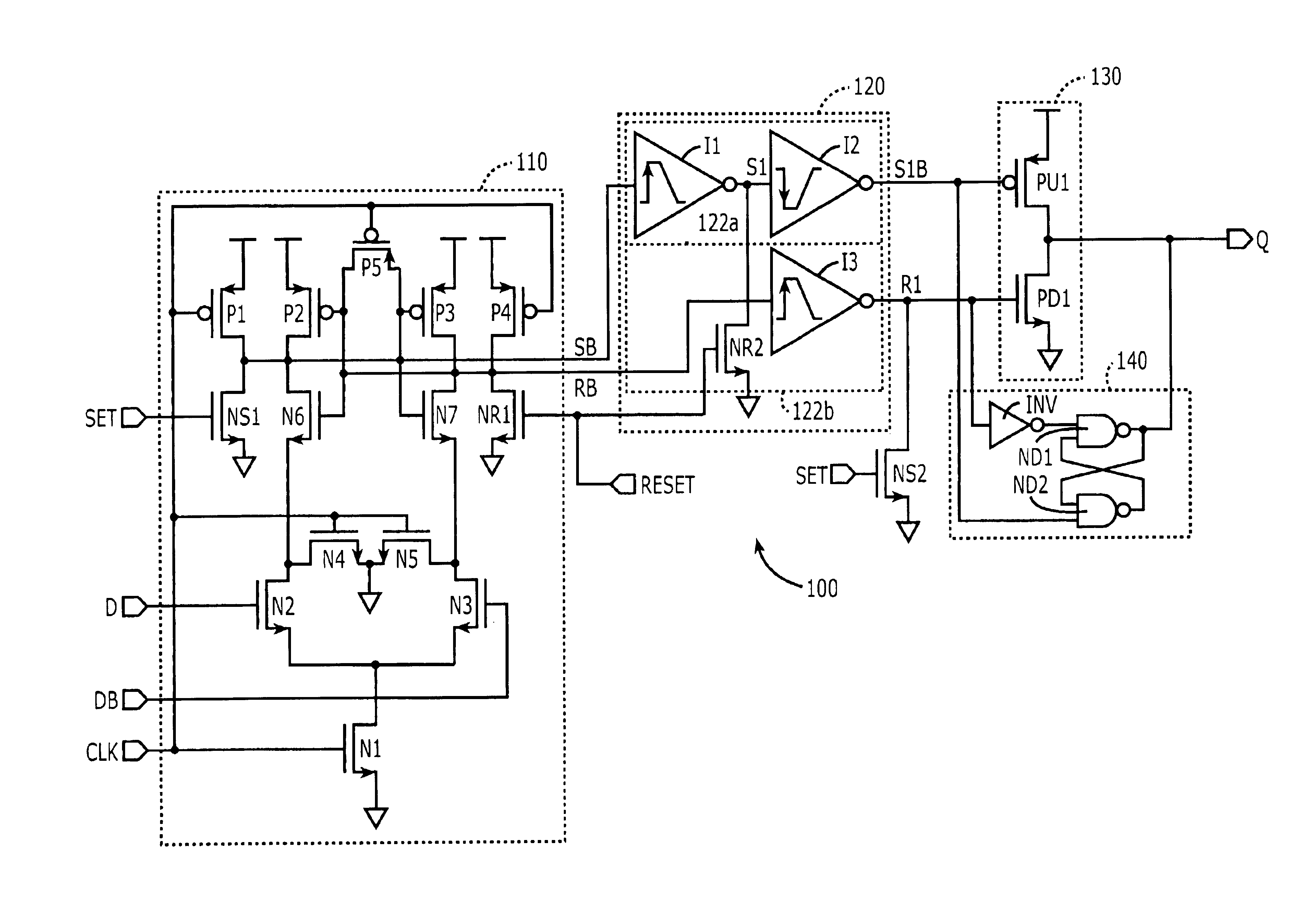
[0016]The present invention now will be described more fully herein with reference to the accompanying drawings, in which preferred embodiments of the invention are shown. This invention may, however, be embodied in many different forms and should not be construed as being limited to the embodiments set forth herein; rather, these embodiments are provided so that this disclosure will be thorough and complete, and will fully convey the scope of the invention to those skilled in the art. Like reference numerals refer to like elements throughout and signal lines and signals thereon may be referred to by the same reference characters. Signals may also be synchronized and / or undergo minor boolean operations (e.g., inversion) without being considered different signals. The suffix B (or prefix symbol “ / ”) to a signal name may also denote a complementary data or information signal or an active low control signal, for example.

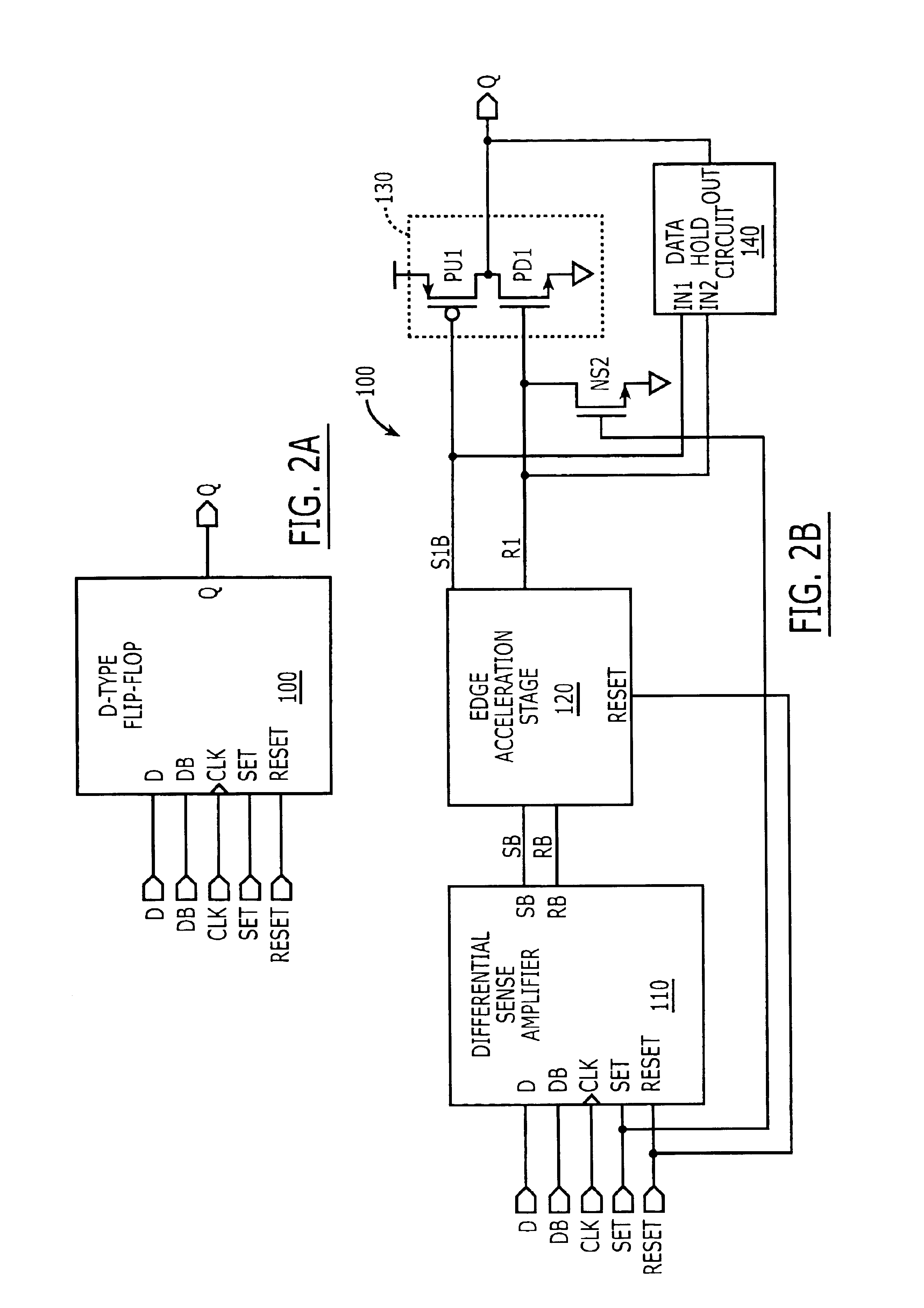
[0017]Referring now to FIGS. 2A-2B, a clocked sense amplifier flip...


PUM


Abstract

Flip-flop devices provide fast clock-to-Q timing that exploits the pulsed nature of outputs generated by a clocked sense amplifier. These flip-flop devices include an output stage, which has a PMOS pull-up transistor and an NMOS pull-down transistor therein, and a clocked sense amplifier at an input stage. The clocked sense amplifier is configured to generate first and second data output signals ( / SET and / RESET). These data output signals are provided to a signal edge acceleration stage. This signal edge acceleration stage is configured to generate the pull-up and pull-down control pulses in response to the first and second data output signals, respectively. This leading edge acceleration stage includes a pull-up buffer having an odd (even) number of inverters therein that are skewed to accelerate the leading edge of the pull-up control pulse relative to a trailing edge of the pull-up control pulse. The leading edge acceleration stage also includes a pull-down buffer having an even (odd) number of inverters therein that are skewed to accelerate the leading edge of the pull-down control pulse relative to a trailing edge of the pull-down control pulse. Accordingly, the pull-up buffer accelerates the clock-to-Q timing when driving Q high and the pull-down buffer accelerates the clock-to-Q timing when driving Q low.

Description

FIELD OF THE INVENTION[0001]The present invention relates to integrated circuit devices and, more particularly, to integrated circuit devices that latch data provided to integrated circuit loads.BACKGROUND OF THE INVENTION[0002]Flip-flop devices are one of the fundamental building blocks of digital integrated circuits and systems. Typical high performance flip-flop devices include sense amplifier flip-flops (SAFF), hybrid latch flip-flops (HLFF) and semi-dynamic flip-flops (SDFF). One conventional sense amplifier flip-flop is described in an article by B. Nikolic et al. entitled “Sense Amplifier-Based Flip Flop,” IEEE International Solid-State Circuits Conference, ISSCC99, Paper TP 16.5, pp. 282-283 and 468 (1999). As illustrated by FIG. 16.5.2 of the Nikolic et al. article, the SAFF integrates logic into the flip-flop in order to generate output signals Q and / Q having equal rising and falling transitions. This SAFF is more fully illustrated by U.S. Pat. Nos. 6,633,188 B1 and 6,107...

Claims


Application Information

Patent Timeline
IPC IPC(8): H03K3/356H03K3/012H03K3/00
CPCH03K3/012H03K3/356139H03K3/356182H03K3/356191
Inventor HAYTER, RUSSELL
Owner INTEGRATED DEVICE TECH INC
Learn More