Timing compensation in a self-servowriting system

a self-servowriting and timing compensation technology, applied in the field of magnetic disk drives, can solve problems such as errors due to amplification of spindle harmonics

Active Publication Date: 2005-08-02
WESTERN DIGITAL TECH INC
View PDF7 Cites 137 Cited by
  • Summary
  • Abstract
  • Description
  • Claims
  • Application Information

AI Technical Summary

Benefits of technology

[0006]The present invention solves these and other problems by providing multi-dimensional compensation for phase (timing) control of a Controlled Oscillator (CO) in a self-servowriting system. In one embodiment, a two-dimensional compensator is used to control timing and / or phase while self-servowriting. The compensator has a two input two output structure. The first input is the timing error and the first output is a control signal for a controlled oscillator. The second input is the second output stored from previous operation of writing the servo track. When a track is written, the data from the second output of the compensator is stored in a lookup table and used as the second input of the compensator when the next track is written. This process is repeated while writing other servo tracks. The compensator parameters are designed to avoid timing error propagation (e.g., amplification of disturbance components in the phase of the written track) during the self-servowriting process.

Problems solved by technology

When a conventional Phase Locked Loop (PLL) compensator is used, errors arise due to amplification of spindle harmonics and other timing disturbances of similar frequency spectrum in the written track due to the peaking nature of the closed-loop transfer function.

Method used


Image

  • Timing compensation in a self-servowriting system
  • Timing compensation in a self-servowriting system
  • Timing compensation in a self-servowriting system

Examples


Embodiment Construction

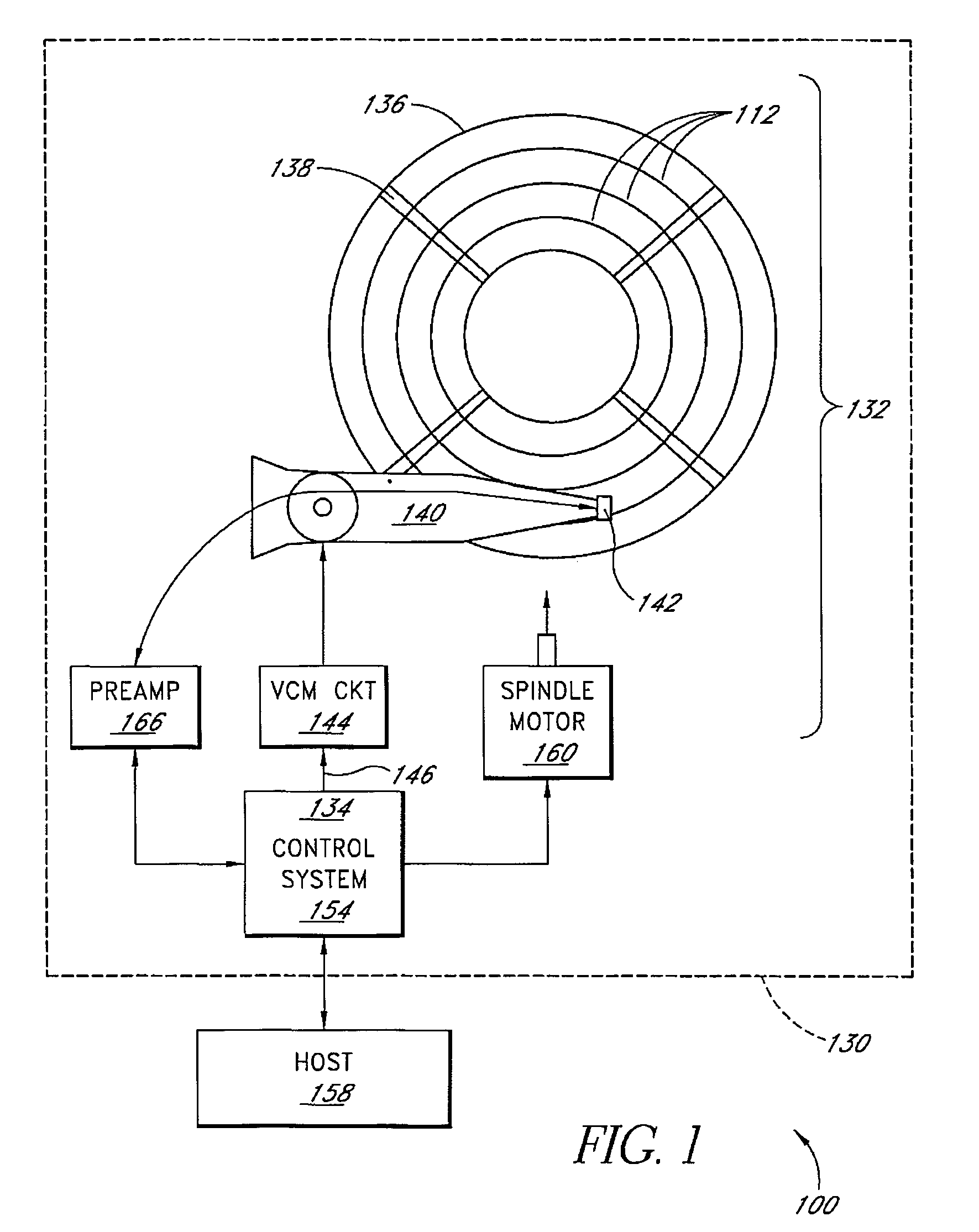
[0016]FIG. 1 is a block diagram if a self-servowriting system 100 including a disk drive 130 coupled to a host 158. The disk drive 130 includes a rotating magnetic medium 136. The disk drive 130 has a head disk assembly (HDA) 132 and a servo controller 134. The HDA 132 includes a rotating magnetic disk 136 having, after servo writing, distributed position information in a plurality of servo wedges 138 written on circular servo tracks 112. A rotary actuator 140 pivots relative to a base and that carries a transducer head 142 that periodically reads the position information from the servo wedges, and a voice coil motor (VCM) circuit 144 that includes a voice coil motor coupled to the rotary actuator and that responds to a control effort signal 146. The sampled servo controller 134 periodically adjusts the control effort signal during a track-following operation based on position information. In one embodiment, the transducer head has a read element 148 and an offset write element 150....


PUM

PropertyMeasurementUnit
voltageaaaaaaaaaa
currentaaaaaaaaaa
densitiesaaaaaaaaaa

Abstract

A method is disclosed for defining tracks on a rotating magnetic disk medium of a disk drive. Reference tracks are followed using a servo control loop while writing servo patterns defining a first target servo track. The servo control loop includes a two-dimensional digital state compensator having a first input that receives timing error signals, a first output that generates control signals for a controlled oscillator, a second output that generates timing state variables, and a second input that receives stored timing state variables. The first target track is followed using the servo control loop while servo patterns are written, and while the stored timing state variables corresponding to the servo patterns defining the first target track are applied to the second input.

Description

BACKGROUND OF THE INVENTION[0001]1. Field of the Invention[0002]The present invention relates to magnetic disk drives, and more particularly, to self-servowriting of tracks on a rotating magnetic disk medium.[0003]2. Description of the Related Art[0004]The writing of servo track information on a magnetic disk medium is a critical process in the manufacture of a disk drive. Conventionally, servo track information is written with a specialized servowriting instrument mounted on a large granite block to minimize external vibration effects. Increasing track densities and decreasing disk size has led to the investigation of self-servowriting techniques.[0005]In self-servowriting, the read head track-follows on a track and writes the servo information for a subsequent track, which then becomes the reference track for the next track. The process is repeated until all servo tracks are written. When a conventional Phase Locked Loop (PLL) compensator is used, errors arise due to amplification...

Claims


Application Information

Patent Timeline
Patent Type & Authority Patents(United States)
IPC IPC(8): G11B5/596
CPCG11B5/59633G11B5/59655
Inventor MELKOTE, HEMANTCLOKE, ROBERT L.
Owner WESTERN DIGITAL TECH INC
Why Eureka
Try Eureka