AC sensing method memory circuit

a memory circuit and sensing method technology, applied in the direction of memory adressing/allocation/relocation, digital storage, instruments, etc., can solve the problems of increasing the number of cells, increasing the delay, and increasing the capacitance, so as to narrow the threshold voltage distribution of memory cells

Inactive Publication Date: 2005-08-02
FUJITSU LTD
View PDF2 Cites 29 Cited by
  • Summary
  • Abstract
  • Description
  • Claims
  • Application Information

AI Technical Summary

Benefits of technology

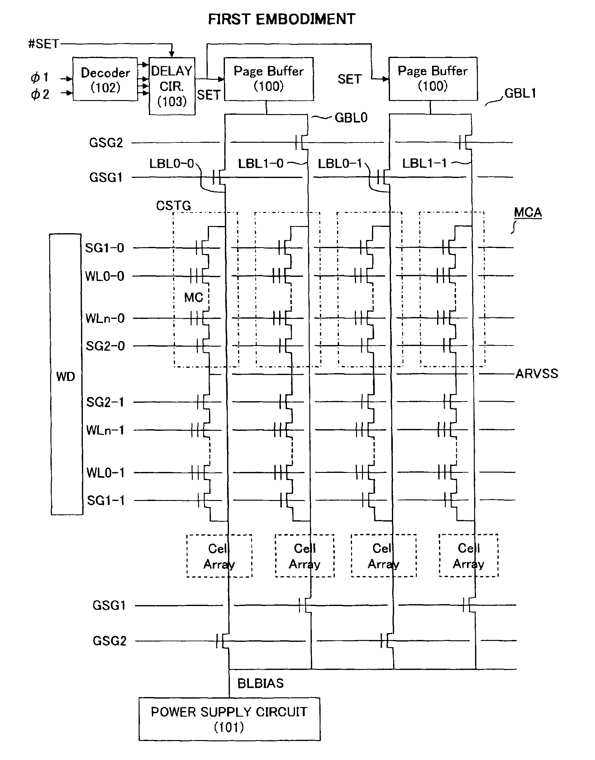
[0020]Accordingly, it is an object of the present invention to provide an AC sensing method memory circuit that is capable of performing detection of cell data b...

Problems solved by technology

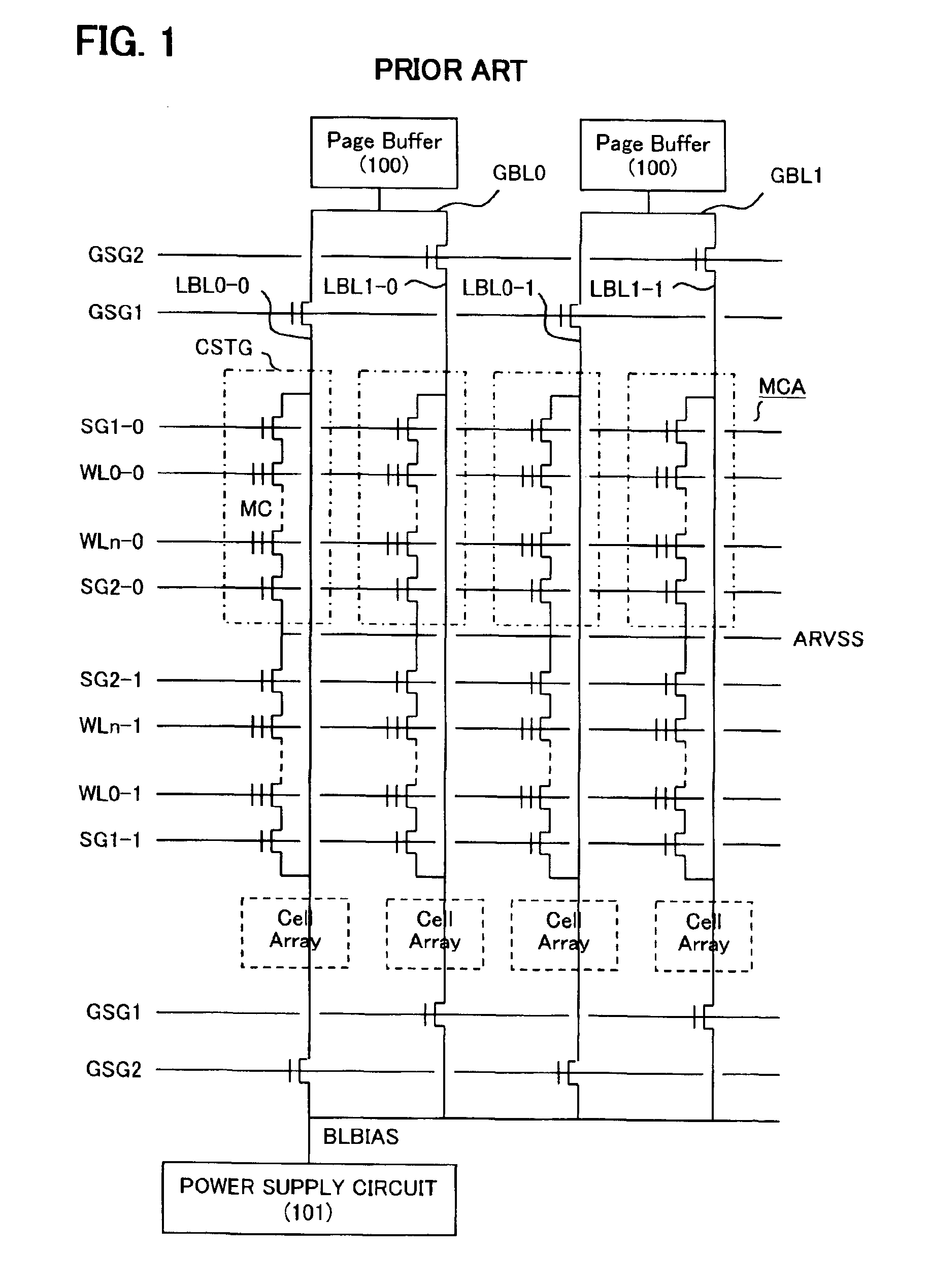
On the other hand, an increased capacity involves longer word lines and bit lines in the cell array and an increase in the number of cells which are connected to these lines, which results in a larger capacitance.
Such an increase in the RC (Resistance and Capacitance) value results in an increase in the delay when the word lines are driven by a word driver and when select lines are driven, together with an increase in the delay in the discharge of a bit line potential by a cell current.
In addition, in a memory cell that is disposed close to the word driver for driving the word lines, the rise in the word line and in the select line of the cell string is rapid, meaning that the initiation of the disch...

Method used


Image

  • AC sensing method memory circuit
  • AC sensing method memory circuit
  • AC sensing method memory circuit

Examples


second embodiment

[Second Embodiment]

[0066]FIG. 13 is an outline constitutional view of the memory circuit according to the second embodiment. In this embodiment, in addition to an ordinary memory cell array MCA, a reference memory cell array RMCA is provided in the position furthest from the word driver WD. Further, provided in the reference memory cell array are: reference bit lines, and reference memory cells disposed in the positions of intersection between the reference bit lines and the word lines, wherein the sense timing of the page buffers is determined in accordance with the potential produced when the reference bit lines are discharged by cell currents of reference memory cells that belong to the selected word lines.

[0067]FIG. 14 shows a detail circuit diagram of the memory circuit according to the second embodiment. The reference memory cell array RMCA is provided on the opposite side to the word driver of the ordinary memory cell array MCA. The reference memory cell array RMCA of FIG. 14...


PUM


Abstract

The present invention is a memory circuit, comprises: a memory cell array including a plurality of bit lines, a plurality of word lines, and a plurality of memory cells disposed in the positions of intersection between the bit lines and the word lines; and a page buffer, which is connected to the bit line and which detects memory cell data by judging with predetermined sense timing the potential of the bit line when a pre-charged bit line potential is discharged in accordance to a cell current of a selected memory cell. Further the sense timing differs in accordance with the position of the selected memory cell in the memory cell array.

Description

CROSS-REFERENCE TO RELATED APPLICATIONS[0001]This application is based upon and claims the benefit of priority from the prior Japanese Patent Application No. 2002-247345, filed on Aug. 27, 2002, the entire contents of which are incorporated herein by reference.BACKGROUND OF THE INVENTION[0002]1. Field of the Invention[0003]The present invention relates to an AC sensing method memory circuit, and more particularly to a memory circuit capable of suitably detecting data of memory cells even though the data capacity is increased.[0004]2. Description of the Related Art[0005]There has been an increasing demand to increase the capacity of nonvolatile semiconductor memory, which is one kind of semiconductor memory circuit, and to reduce the voltages thereof. The voltage reduction is directed toward the conservation of electric power by enabling operation at lower voltages. This voltage reduction is accompanied by a trend toward a reduction in the cell current that is able to flow in the mem...

Claims


Application Information

Patent Timeline
IPC IPC(8): G11C16/04G11C16/06G11C5/00G11C16/26G11C16/34
CPCG11C16/0483G11C16/26G11C16/3436
Inventor KAWAMURA, SHOICHIYANO, MASARUNIIMI, MAKOTONAGAI, KENJI
Owner FUJITSU LTD
Why Eureka
Try Eureka