Digital-data receiver synchronization

a digital-data receiver and receiver technology, applied in the field of digital-data receivers, can solve the problems of significantly more finesse, significantly more difficult analysis, and substantially worse performance of most demodulators in fading and multipath (dispersive) environments, and achieves a lower sustained bit-error rate, lower gate count, and simple logic design.

Inactive Publication Date: 2005-08-02
UT BATTELLE LLC
View PDF25 Cites 30 Cited by
  • Summary
  • Abstract
  • Description
  • Claims
  • Application Information

AI Technical Summary

Benefits of technology

[0027]It is another object of this invention to provide a digital-data receiver apparatus and method wherein frequency and phase errors are minimized.
[0038]Another object of the current invention is a method of providing improved digital-data receiver synchronization comprising the steps of: providing a plurality of memory devices for receiving multiple timing signals, each of the plurality of memory devices comprising a composite phase-frequency detector; and, interconnecting the memory devices with a feedback means for cross-coupling certain signals produced by the memory devices; wherein the receiver produces fast lock-up times in moderately to severely noisy conditions and avoids loss of lock in all but the most severe fading, interference, and / or multipath conditions.

Problems solved by technology

The performance (i.e., bit error rate versus signal-to-noise ratio) of most demodulators in fading and multipath (dispersive) environments is substantially worse than in pure-AWGN channels, is much more difficult to analyze, and in practice requires significantly more finesse to achieve good link performance.
Indeed, most of the mathematical simulations of fading channels are made assuming perfect receiver synchronization is somehow achieved; unfortunately, this in reality is unjustifiably optimistic.
This scheme is directed solely at time-division multiplexed systems (e.g., GSM) and is not broadly applicable to other types of systems such as spread-spectrum.
Further, this patent makes no mention of PLL-based systems (single or multiple) and has no applicability to synchronization methods.
Although the techniques herein are useful for the manufacture of receiver hardware, they only deal with noise generated internal to the receiver itself and do not in any way address RF link noise and degradations affecting the input signal from the antenna.
This technique does not employ any PLL hardware and thus is not relevant to the instant case.
In general, good multipath rejection is difficult to achieve except in spread-spectrum or other dispersive communications systems; even in these formats, multipath causes noticeable degradations in overall system performance.
The presence of multipath components in the received signal distorts and delays the peak of the AF (best correlation point), which causes an error when the AF is employed in a delay-lock loop (a form of PLL) to measure the precise code phase (and thus the pseudorange) from a GPS satellite.
Since in conventional PLL circuits, a fast response time requires a large control-signal bandwidth, this constraint is directly at odds with a low phase-noise level (requires heavy control-signal filtering and thus low bandwidth).
While each of the foregoing may have some utility for the intended applications thereof, none of them directly address or effectively solve the problems noted initially above.

Method used


Image

  • Digital-data receiver synchronization
  • Digital-data receiver synchronization
  • Digital-data receiver synchronization

Examples


Embodiment Construction

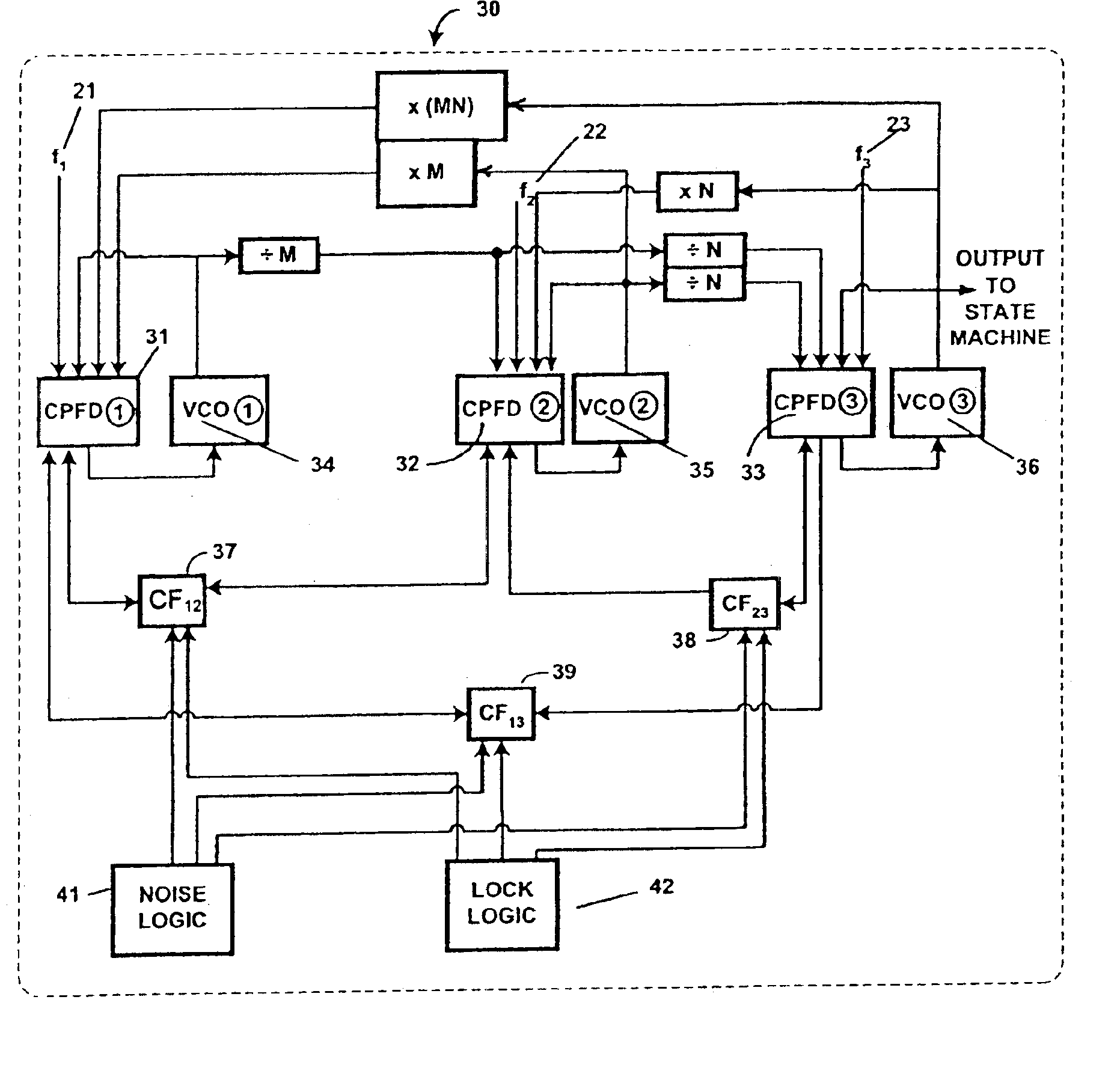
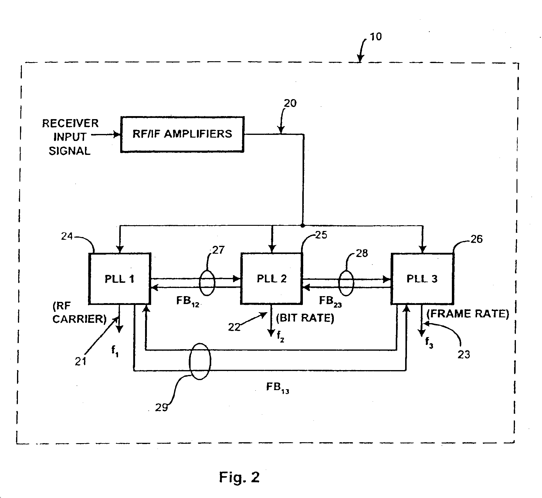
[0047]The fundamental intent of the invention is, as described above, to exploit the timing structure in a typical digital data transmission by concurrently and corporately synchronizing (locking) to each of the salient timing components in the data stream. When one or more of these components is corrupted by noise, multipath, interference, or other channel degradations, the set of PLLs “fills in” the missing synchronization information by regenerating the necessary signal(s) from a combination of the remaining (uncorrupted) components.

[0048]While applicable to highly complex transmitter-receiver systems, the basic principles of the current invention may be generally explained by reference to a simple system. For the sake of simplicity, a transmitter is assumed to emit three types of data-related signals, each at a distinct frequency. These three signal-frequency components are the carrier, the data bit rate, and the data frame rate. A more complex system, to which the current inven...


PUM


Abstract

Digital-data receiver synchronization is provided with composite phase-frequency detectors, mutually cross-connected comparison feedback or both to provide robust reception of digital data signals. A single master clock can be used to provide frequency signals. Advantages can include fast lock-up time in moderately to severely noisy conditions, greater tolerance to noise and jitter when locked, and improved tolerance to clock asymmetries.

Description

CROSS REFERENCE TO RELATED APPLICATION[0001]This application is a divisional of, and claims a benefit of priority under 35 U.S.C. § 120 from U.S. Ser. No. 09 / 653,788, filed Sep. 1, 2000 the entire contents of which are hereby expressly incorporated by reference for all purposes.STATEMENT AS TO RIGHTS TO INVENTIONS MADE UNDER FEDERALLY-SPONSORED RESEARCH OR DEVELOPMENT[0002]This invention was made with United States Government support awarded by the United States Department of Energy under prime contract No. DE-AC05-00OR22725 to UT-Battelle, LLC. The United States Government has certain rights in this invention.FIELD OF THE INVENTION[0003]The current invention relates generally to digital-data receivers, and particularly to an improved digital-data receiver using multiple cross-coupled synchronization loops.BACKGROUND OF THE INVENTION[0004]1. Field of the Invention[0005]Most digital transmitter devices utilize separate frequency-reference sources (e.g., crystal oscillators, SAW reson...

Claims


Application Information

Patent Timeline
Patent Type & Authority Patents(United States)
IPC IPC(8): H03L7/08H03L7/087H03L7/07H03L7/191H03L7/16H03L7/23H04J3/06H03L7/089
CPCH03L7/07H03L7/087H03L7/0891H03L7/191H03L7/23H04J3/0685
Inventor SMITH, STEPHEN F.TURNER, GARY W.
Owner UT BATTELLE LLC
Why Eureka
Try Eureka