Illumination system

a technology of illumination system and focusing lens, which is applied in the direction of lighting and heating apparatus, picture reproducers using projection devices, instruments, etc., can solve the problems of inability to use proper adjustment mechanism, inability to effectively centralize light beams reflected by reflective mirrors, and failure to overcome the above drawbacks, so as to enhance the performance of the illumination system, the effect of minimizing power loss and overheating the problem of assembling error

Active Publication Date: 2016-01-07
DELTA ELECTRONICS INC
View PDF2 Cites 5 Cited by
  • Summary
  • Abstract
  • Description
  • Claims
  • Application Information

AI Technical Summary

Benefits of technology

[0006]An object of the present invention provides an illumination system. The illumination system comprises a light source, a reflective mirror, a fixing structure, and an adjusting mechanism. By the adjusting mechanism, the location and the angle of the reflective mirror relative to the optical axis of the light source is adjusted. Consequently, the light beam reflected by the reflective mirror can be effectively guided to the focusing element. Consequently, the performance of the illumination system is enhanced, and the power loss and overheated problem from the assembling error are minimized.
[0007]Another object of the present invention provides an illumination system for increasing the imaging quality and luminance of a projection device.

Problems solved by technology

However, due to the assembly tolerance of the light-emitting elements and the reflective mirrors or the characteristics of the light-emitting elements (e.g. the beam angle), the light beams reflected by the reflective mirrors cannot be effectively centralized and guided to the same focusing lens.
Moreover, since no proper adjusting mechanism can be used to adjust the reflective mirrors, the above drawbacks fail to be overcome.
Under this circumstance, the power loss is increased, and the utilization efficiency of the illumination system is deteriorated.
Moreover, since the intensity of the light beams introduced into the projection device is insufficient, the image quality and the luminance are adversely affected.

Method used


Image

  • Illumination system
  • Illumination system
  • Illumination system

Examples


Embodiment Construction

[0019]The present invention will now be described more specifically with reference to the following embodiments. It is to be noted that the following descriptions of preferred embodiments of this invention are presented herein for purpose of illustration and description only. It is not intended to be exhaustive or to be limited to the precise form disclosed.

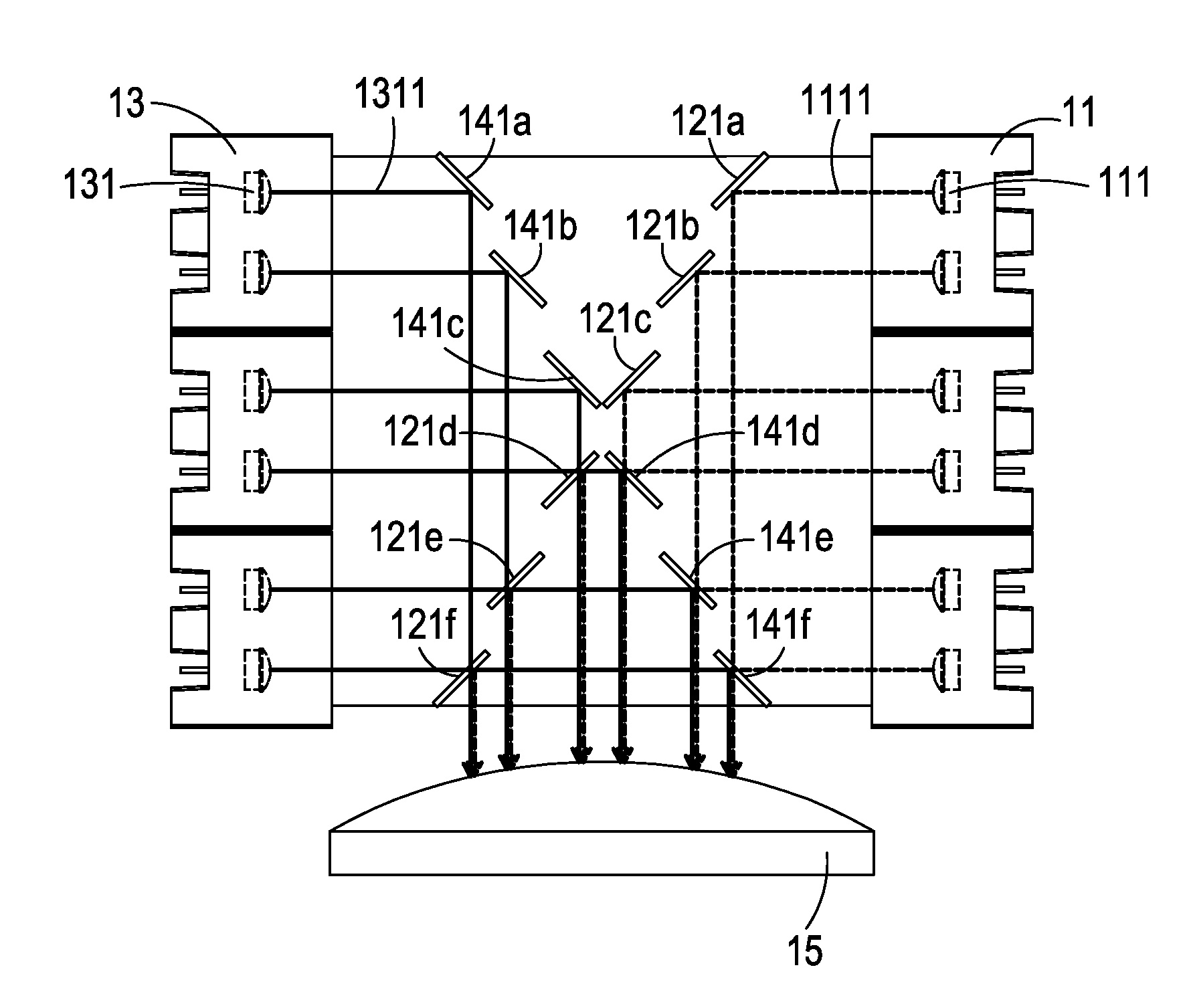
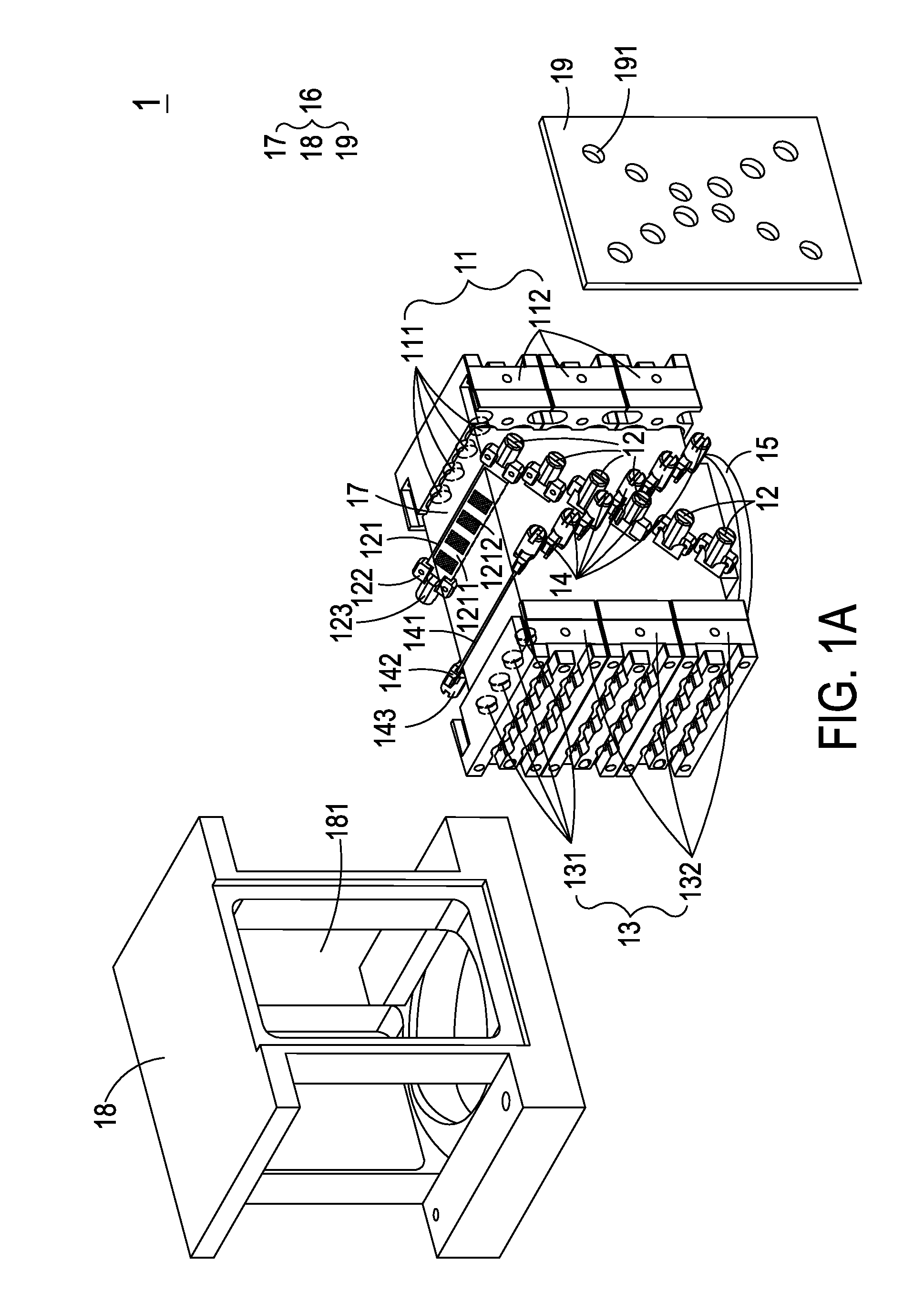
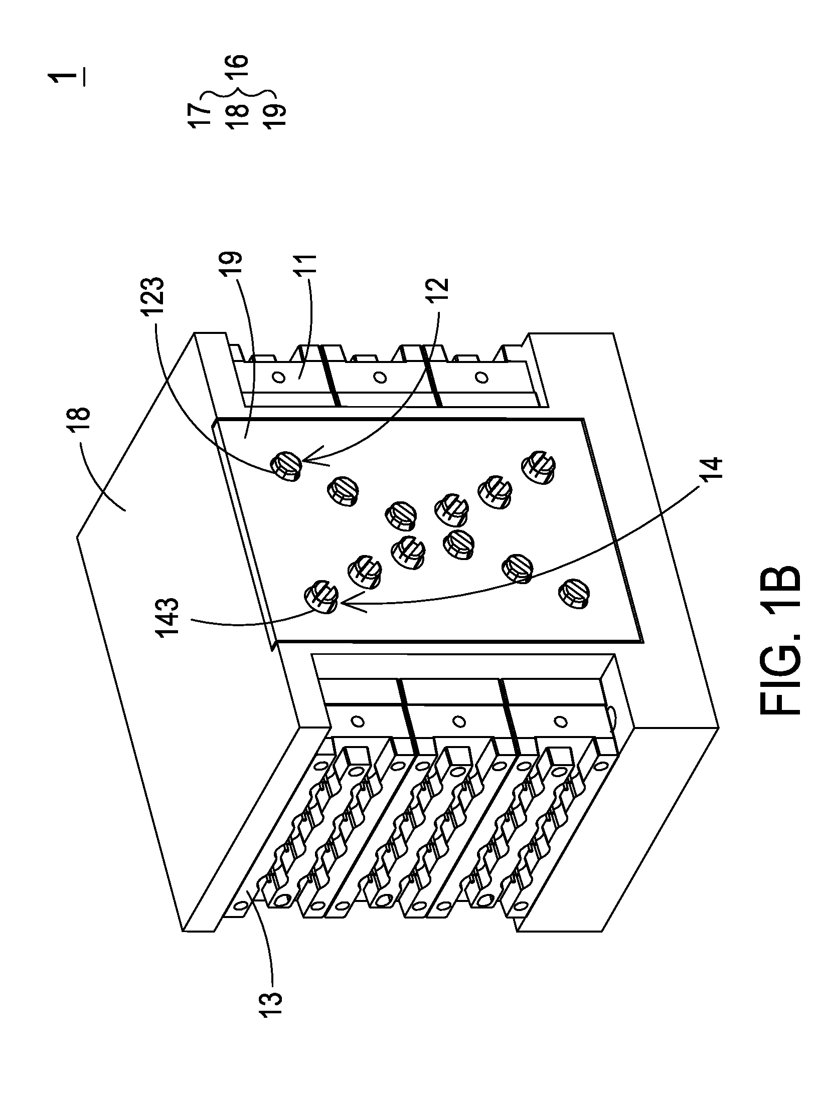
[0020]Please refer to FIG. 1A, FIG. 1B, FIG. 2, FIG. 3A and FIG. 3B. FIG. 1A is a schematic exploded view illustrating an illumination system according to a first embodiment of the present invention. FIG. 1B is a schematic assembled view of the illumination system of FIG. 1A. FIG. 2 schematically illustrates a first reflective mirror module of the illumination system according to the first embodiment of the present invention. FIGS. 3A and 3B schematically illustrate the optical paths of the light beams of the illumination system according to the first embodiment of the present invention.

[0021]The illumination system 1 of the pres...


PUM


Abstract

An illumination system includes a first light source module and a first reflective mirror module. The first light source module includes plural first light sources for emitting plural first light beams, respectively. The first reflective mirror module includes at least one first reflective mirror, at least one first fixing structure, and at least one first adjusting mechanism. The first reflective mirror is located at a first optical axis of the plural first light sources. The at least one first fixing structure is used for fixing the first reflective mirror. The first adjusting mechanism is connected with the first fixing structure. By moving or rotating the first adjusting mechanism, a location and an angle of the first reflective mirror relative to the first optical axis are correspondingly changed, so that the first light beam is reflected by the first reflective mirror and guided along a specified optical path.

Description

FIELD OF THE INVENTION[0001]The present invention relates to an illumination system, and more particularly to an illumination system having an adjusting mechanism for adjusting a reflective mirror module.BACKGROUND OF THE INVENTION[0002]In recent years, a variety of projectors have been widely used in various video applications. For example, projectors can be used for making presentations, holding meetings or giving lectures in classrooms, boardrooms, conference rooms or home theaters. By the projector, an image signal from an image signal source can be enlarged and shown on a projection screen. For reducing power loss and overall volume and increasing the image quality, the illumination system of the current projector employs a solid-state light-emitting element (e.g. light emitting diode or laser diode) to replace the conventional high intensity discharge (HID) lamp or ultra-high pressure (UHP) mercury lamp.[0003]Generally, for increasing the total light amount, plural solid-state...

Claims


Application Information

Patent Timeline
Patent Type & Authority Applications(United States)
IPC IPC(8): G03B21/20G02B7/182G03B21/14H04N9/31
CPCG03B21/2046G03B21/142H04N9/3164G03B21/2066G02B7/1822G03B21/2013G02B27/108G02B27/14
Inventor CHEN, CHING-LIANG
Owner DELTA ELECTRONICS INC
Why Eureka
Try Eureka