MAC protocol for optical packet-switched ring network

a packet-switched ring network and protocol technology, applied in the field of communication systems, can solve the problems that existing network architectures and protocols may not be able to utilize the enhanced throughput provided by wdma technology

Inactive Publication Date: 2005-08-02
AMERICAN TELEPHONE & TELEGRAPH CO
View PDF17 Cites 20 Cited by
  • Summary
  • Abstract
  • Description
  • Claims
  • Application Information

AI Technical Summary

Problems solved by technology

Existing network architectures and protocols may not be able to utilize the enhanced throughput provided by WDMA technology.

Method used


Image

  • MAC protocol for optical packet-switched ring network
  • MAC protocol for optical packet-switched ring network
  • MAC protocol for optical packet-switched ring network

Examples


Embodiment Construction

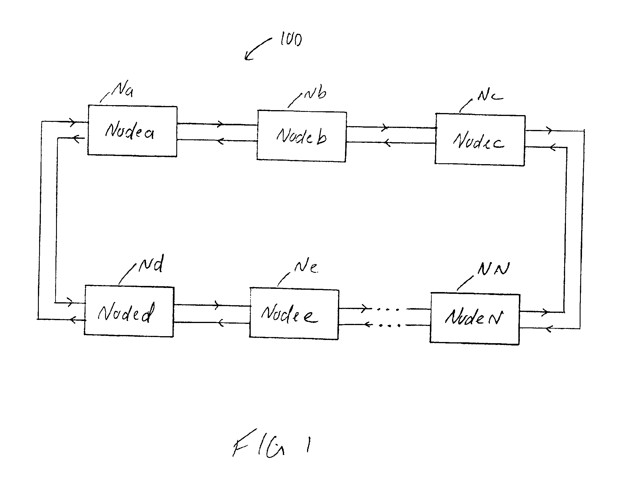
[0018]FIG. 1 shows an exemplary ring network 100 having an architecture that enhances the throughput of high-capacity packet-switched ring networks in accordance with the present invention. In general, network nodes Na-Nn access the entire link capacity by transmitting and receiving packets in parallel on all available wavelengths. Packets are added and dropped from the ring by optical switches, which avoid the need for problematic fast tunable receivers. The bandwidth allocation of the network is more flexible than in networks having fixed tuned or slow tunable receivers. In one embodiment, a MAC protocol for the packet-switched ring network is based on credits and a dynamic admission control algorithm requires minimal processing complexity and can follow fast traffic changes.

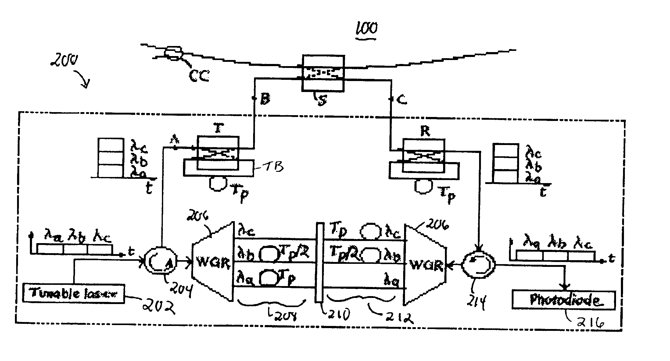
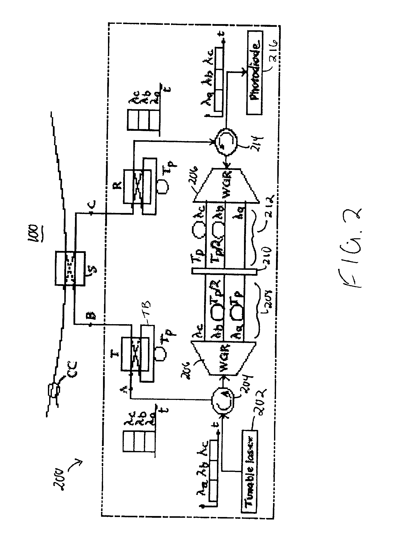
[0019]FIG. 2 shows further details of an exemplary node 200 of a WDMA packet-switched ring network 100 in accordance with the present invention. The network architecture is based upon “wavelength stacking,” wh...


PUM


Abstract

A flexible, credit-based MAC protocol along with an admission algorithm enhance the throughput capacity of a packet switched WDMA ring network utilizing packet wavelength stacking and unstacking.

Description

CROSS REFERENCE TO RELATED APPLICATIONS[0001]The present application claims priority from U.S. Provisional Patent Application Nos. 60 / 239,766, filed on Oct. 12, 2000 and 60 / 240,464, filed on Oct. 13, 2000, which are incorporated herein by reference.STATEMENT REGARDING FEDERALLY SPONSORED RESEARCH[0002]Not Applicable.FIELD OF THE INVENTION[0003]The present invention relates generally to communication systems and, more particularly, to optical communication networks.BACKGROUND OF THE INVENTION[0004]As is known in the art, an optical ring network includes a plurality of nodes connected by an optical fiber so as to form a ring that interconnects each of the nodes. Ring networks can include a plurality of fiber rings for network protection. Regional access networks with ring topologies are attractive because they easily recover from a single failure. Also, ring networks allow simple synchronization of geographically distant nodes. Media Access Control (MAC) protocols in ring networks ens...

Claims


Application Information

Patent Timeline
Patent Type & Authority Patents(United States)
IPC IPC(8): H04Q11/00H04J14/02H04B10/27H04B10/275H04J14/00H04J14/08H04L12/42H04L12/56H04Q11/04
CPCH04J14/0206H04J14/021H04J14/0212H04J14/0213H04J14/0283H04J14/0286H04Q11/0005H04Q11/0066H04Q11/0478H04J14/0249H04J14/0241H04J14/0245H04J14/0209H04J14/0227H04J14/083H04L2012/5632H04L2012/5649H04L2012/5679H04Q2011/002H04Q2011/0022H04Q2011/0024H04Q2011/0033H04Q2011/0035H04Q2011/0052H04Q2011/0064H04Q2011/0075H04Q2011/0086H04Q2011/0092
Inventor BORODITSKY, MIKHAILFRIGO, NICHOLAS J.SMILJANIC, ALEKSANDRA
Owner AMERICAN TELEPHONE & TELEGRAPH CO
Why Eureka
Try Eureka