Tool turret

a tool turret and tool technology, applied in the field of tool turrets, to achieve the effect of reducing maintenance costs, cost-effective, and occupying even less structural spa

Inactive Publication Date: 2005-08-09
ZEITFRACHT GMBH & CO KGAA
View PDF13 Cites 31 Cited by
  • Summary
  • Abstract
  • Description
  • Claims
  • Application Information

AI Technical Summary

Benefits of technology

[0006]Objects of the present invention are to provide an improved to tool turret having the advantages of conventional tool turrets and being cost-effective, taking up even less structural space, and permitting reduction of maintenance costs as a result of increase in reliability of operation.

Problems solved by technology

The motors used for the purpose may be provided for direct driving of the machine tool and are very compact.

Method used


Image

  • Tool turret
  • Tool turret
  • Tool turret

Examples


Embodiment Construction

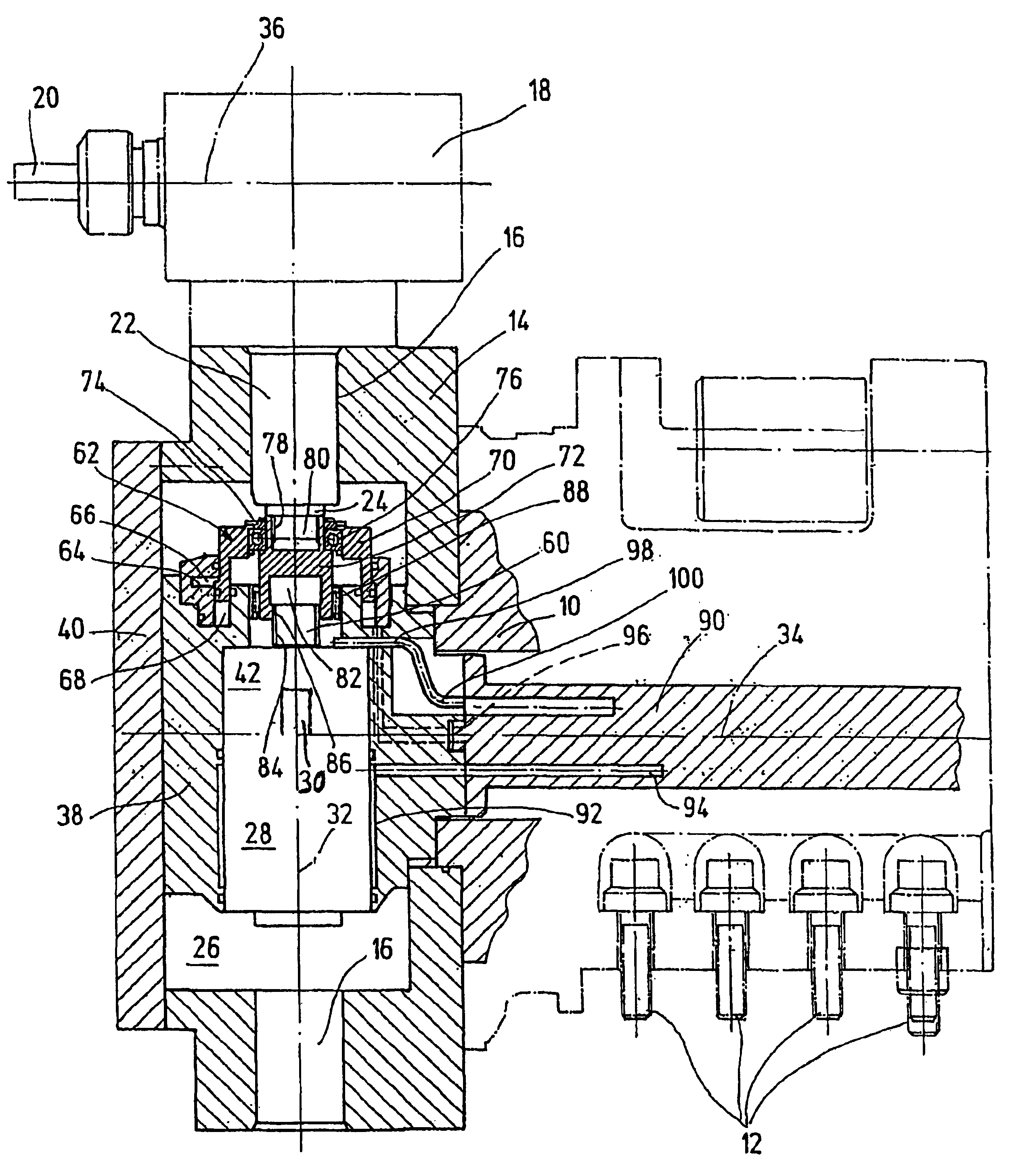
[0019]A tool turret has a housing 10 which is secured in position on a machine tool (not shown), for example, on a slide of such machine tool, by a threaded connection 12. A tool disk or tool carrier is mounted on one end of housing 10 and is rotatable relative to the housing. The tool disk has recesses 16, for machine or machining tools 18, uniformly distributed over its circumference. The tools are configured as tool modules, and have a rotating, metal cutting tool 20, for example, one in the form of a drill or milling cutter. In the exemplary embodiment, the recesses 16 are in the form of drilled holes extending radially. A shank 22 of the machine tool may be inserted into each of these drilled holes. A drive shaft24 projects above such shank 22. The shank 22 may be provided on its external circumference side with positioning gearing (not shown in detail), so that the machining tool 18 may always be secured in position in the recess 16 by a corresponding counterpart in the tool d...


PUM

PropertyMeasurementUnit
speedaaaaaaaaaa
energyaaaaaaaaaa
axial distanceaaaaaaaaaa

Abstract

A tool turret includes a housing (10) for connection to a machine tool, and an electric drive motor (28). A tool disk (14), is mounted to rotate relative to the housing (10) about a longitudinal axis (34), may be fixed in selected angular positions, and has recesses (16) for machining tools (18). At least one rotating machining tool (18) may be driven by the drive motor (28) using shafts (24, 30), extending perpendicular to the longitudinal axis forming the swiveling axis of the tool disk (14). The electric drive motor (28) is arranged within the tool disk (14). The driveshaft (30) from the electric drive (28) is aligned with the driveshaft (24) for the machining tool (18), and is aligned with the driveshaft (24) for the machining tool (18) or extends parallel to it. An economical drive design for machining tools on a tool turret is achieved, with a small installation volume.

Description

FIELD OF THE INVENTION[0001]The present invention relates to a tool turret having a housing to be connected to a machine tool, with an electric drive motor. A tool disk is mounted rotatably relative to the housing, may be fixed in selectable angular positions, and has recesses for machining tools. At least one rotating machining tool is driven by a drive motor by shafts extending perpendicular to the longitudinal axis representing the pivot axis for the tool disk.BACKGROUND OF THE INVENTION[0002]DE 40 18 543 C1 discloses a tool turret having a housing to be connected to the machine tool. The housing has an electric drive motor and a tool disk mounted rotatably relative to the housing. The tool disc has recesses for machining tools, at least one of which is configured for rotatable mounting of the tool. The machining tool may be driven by the drive motor by shafts which are interconnected by gearing. A hollow column is mounted concentrically with the axis of rotation of the tool disk...

Claims


Application Information

Patent Timeline
Patent Type & Authority Patents(United States)
IPC IPC(8): B23Q39/00B23Q39/02
CPCB23Q39/02B23Q2220/002Y10T408/37Y10T483/1733Y10T29/5155Y10T29/5154Y10T74/14Y10T29/5107
Inventor SAUTER, REINERSAHM, DETLEF
Owner ZEITFRACHT GMBH & CO KGAA
Why Eureka
Try Eureka