Muffler for pneumatic hand tool
- Summary
- Abstract
- Description
- Claims
- Application Information
AI Technical Summary
Benefits of technology
Problems solved by technology
Method used
Image
Examples
first embodiment
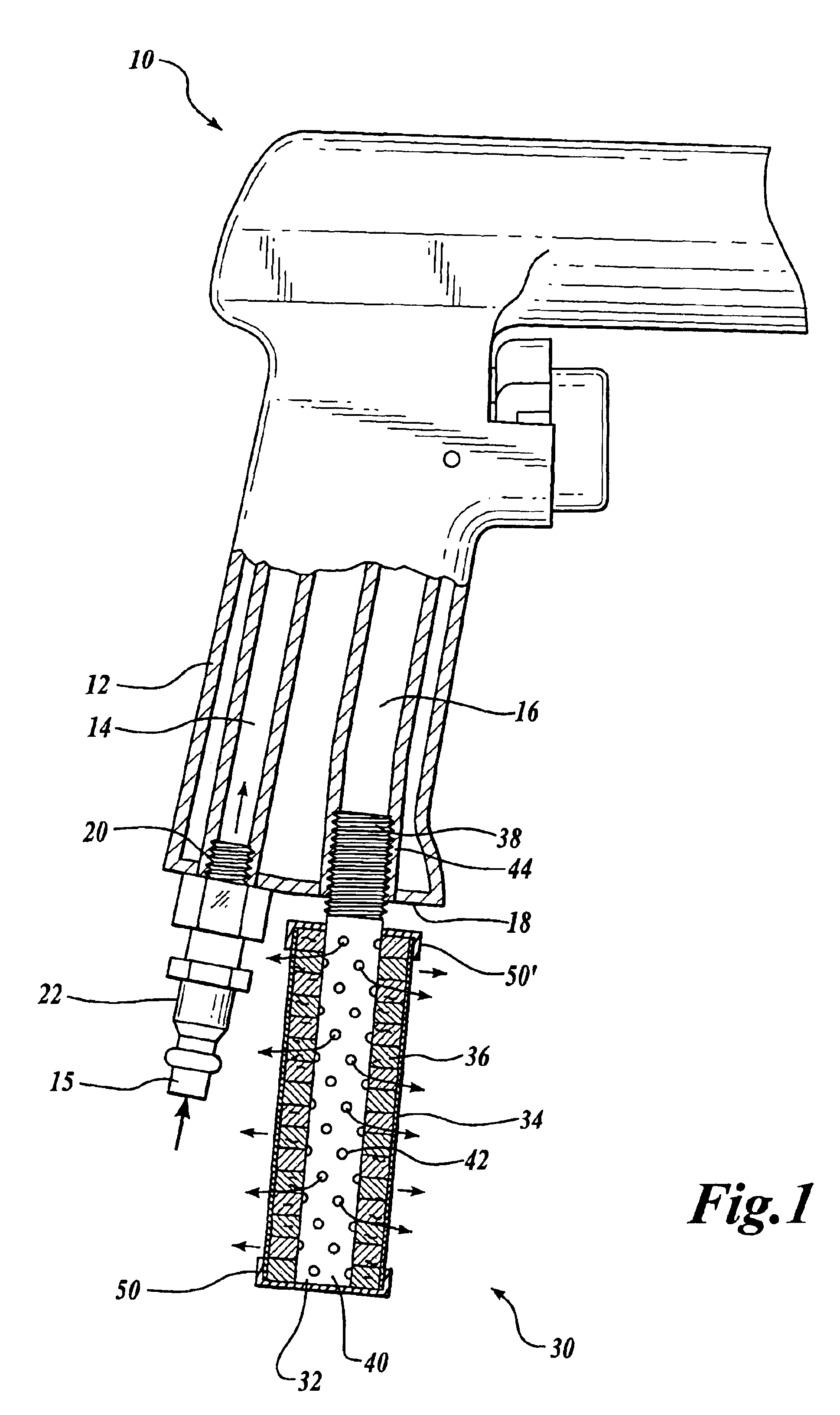
[0030]Shown in FIG. 1 is a muffler 30 formed in accordance with the present invention. FIG. 1 is a partial cutaway drawing. The muffler 30 includes an inner tube 32 having proximal end 38 and distal end 40, an outer sleeve or tube 34, and a number of washers 36. In FIG. 1 at the location of the muffler 30, the inner tube 32 is shown in side view, not cross-section. Each washer 36 is preferably annular with a centered circular inner hole. The inner tube 32 is positioned within the area defined by the stacked washer 36 inner holes. The inner tube 32 is formed from a relatively lightweight rigid material, e.g., plastic, metal alloys, steel, etc. The inner tube 32 includes a plurality of holes 42 distributed about the inner tube 32 along its longitudinal length. In the embodiment of FIG. 1, the inner tube proximal end 38 includes outer threads 44 adapted to screw into corresponding threads formed in the exhaust passage 16 near the exhaust opening. Other known attachment means, however, ...
second embodiment
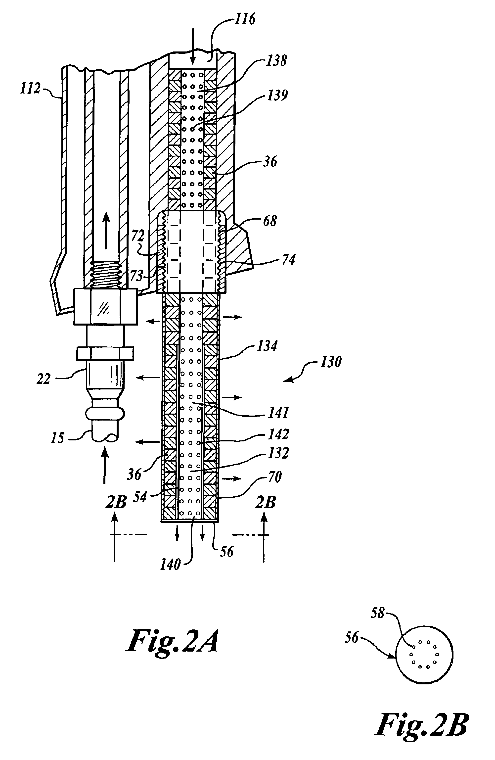
[0036]The second portion 141 is surrounded by washers 36 and an outer sleeve 134. The outer sleeve 134 includes first end 68 and second end 70. The outer sleeve first end 68 is located between the inner tube proximal end 138 and distal end 140. The outer sleeve second end 70 is located near the inner tube distal end 140. The outer sleeve first end 68 is formed as a rigid annular member 72 that includes a threaded outer surface 73. As shown in FIG. 2A, the handle exhaust opening includes mating threads 74 adapted to engage the outer sleeve first end threaded outer surface 73. The mating threads 74 may be formed from a nut that is inserted in the exhaust opening, formed integrally at the exhaust opening during manufacture of the handle 112, formed at the opening after formation of the handle 112, or formed using any other methods available for creating threading. The mating threads 74 of FIG. 2A are provided by a cylindrical nut that is glued, cemented, or heat welded to an existing h...
sixth embodiment
[0043]Shown in FIGS. 6A and 6B is a muffler 430 formed in accordance with the present invention. The muffler 430 includes an inner tube 432 and a number of washers 36. The inner tube 432 is preferably formed as a spring. FIG. 6A is a partial cutaway drawing. At the location of the muffler 430, the inner tube 432 is shown in side view, not in cross-sectional side view. The inner tube 432 is positioned within the area defined by the stacked washer 36 inner holes. When using a spring inner tube 432, the coil thickness and the number of coils per a given length can be tailored to give a particular desired airflow rate. The spring inner tube 432 may be in compression, in tension, or otherwise unloaded. What is important to the present invention is the airflow rate ensuing from the spring—not necessarily the compressive capability of the spring. Therefore, other spring-like shapes may be used.
[0044]In the embodiment of FIG. 6A, the combination of washers 36 and inner tube 432 is inserted ...
PUM
| Property | Measurement | Unit |
|---|---|---|
| Volume | aaaaa | aaaaa |
| Plasticity | aaaaa | aaaaa |
Abstract
Description
Claims
Application Information
 - R&D
- Intellectual Property
- Life Sciences
- Materials
- Tech Scout
- Unparalleled Data Quality
- Higher Quality Content
- 60% Fewer Hallucinations
Browse by: Latest US Patents, China's latest patents, Technical Efficacy Thesaurus, Application Domain, Technology Topic, Popular Technical Reports.
© 2025 PatSnap. All rights reserved.Legal|Privacy policy|Modern Slavery Act Transparency Statement|Sitemap|About US| Contact US: help@patsnap.com


