
High center of gravity stable pneumatic isolator

a pneumatic isolator and high center of gravity technology, applied in the field of pneumatic vibration isolation system, can solve the problems of inability to arbitrarily stiffen the isolator to tilt, the top plate of the isolator cannot be made extremely stiff to tilt, and the -up tilt can involve extremely high torque on the isolator top plate, so as to improve the tilt stability of the payload

Inactive Publication Date: 2005-08-09
TECHN MFG
View PDF27 Cites 23 Cited by
  • Summary
  • Abstract
  • Description
  • Claims
  • Application Information

AI Technical Summary

Benefits of technology

[0011]The present invention improves the tilt stability of a payload by using pneumatic isolators which resist tilting of the payload. The isolator is comprised of a vertical pneumatic isolator assembly suspended by wires. Usually three wires are used and they are grounded.
[0013]When the payload tilts, the top plate must also tilt. Thus, increasing the tilt stiffness of the isolator top plate increases the tilt stiffness for the payload as a whole and reduces tilt. This increase in tilt stiffness can be significant (up to several times stiffer) when compared with an isolation system's normal tilt stiffness (the tilt restoring force generated by the vertical displacements in the system's isolators). Although this increased tilt stiffness degrades the tilt vibration transfer function for a system, tilt noise is known to be small in most environments. The present invention leaves the vertical and horizontal isolator stiffness' virtually unchanged, and thus preserves the isolator's vertical and horizontal vibration transfer function performance.
[0015]Broadly the invention comprises a pneumatic isolator which vertically supports a payload. A minimum of three isolators are used to support a payload. There are at least three wires which are grounded at their tops (fastened to earth via a supporting structure) and connected to a pneumatic isolator assembly at their lower ends. The preferred number of wires is three. The wires prevent the isolator assembly from tilting with horizontal displacements of the payload relative to the earth, while providing a soft suspension to provide horizontal vibration isolation.
[0016]The pneumatic isolator assembly comprises a piston and top plate which supports the payload. The piston is flexibly secured and sealed to a pneumatic chamber by a flexible (rolling rubber) diaphragm. A second pressure chamber is connected to this chamber through a small orifice. As the payload moves in the vertical direction, air is forced to flow between the two chambers through the orifice. This provides a means for damping vertical oscillations of the payload. Fluidic damping (a bob fastened to the piston which moves through a viscous fluid) can also be used to damp motions. Means for reducing tilt by increasing the tilt stiffness of the isolator's supporting top plate are provided in various embodiments.
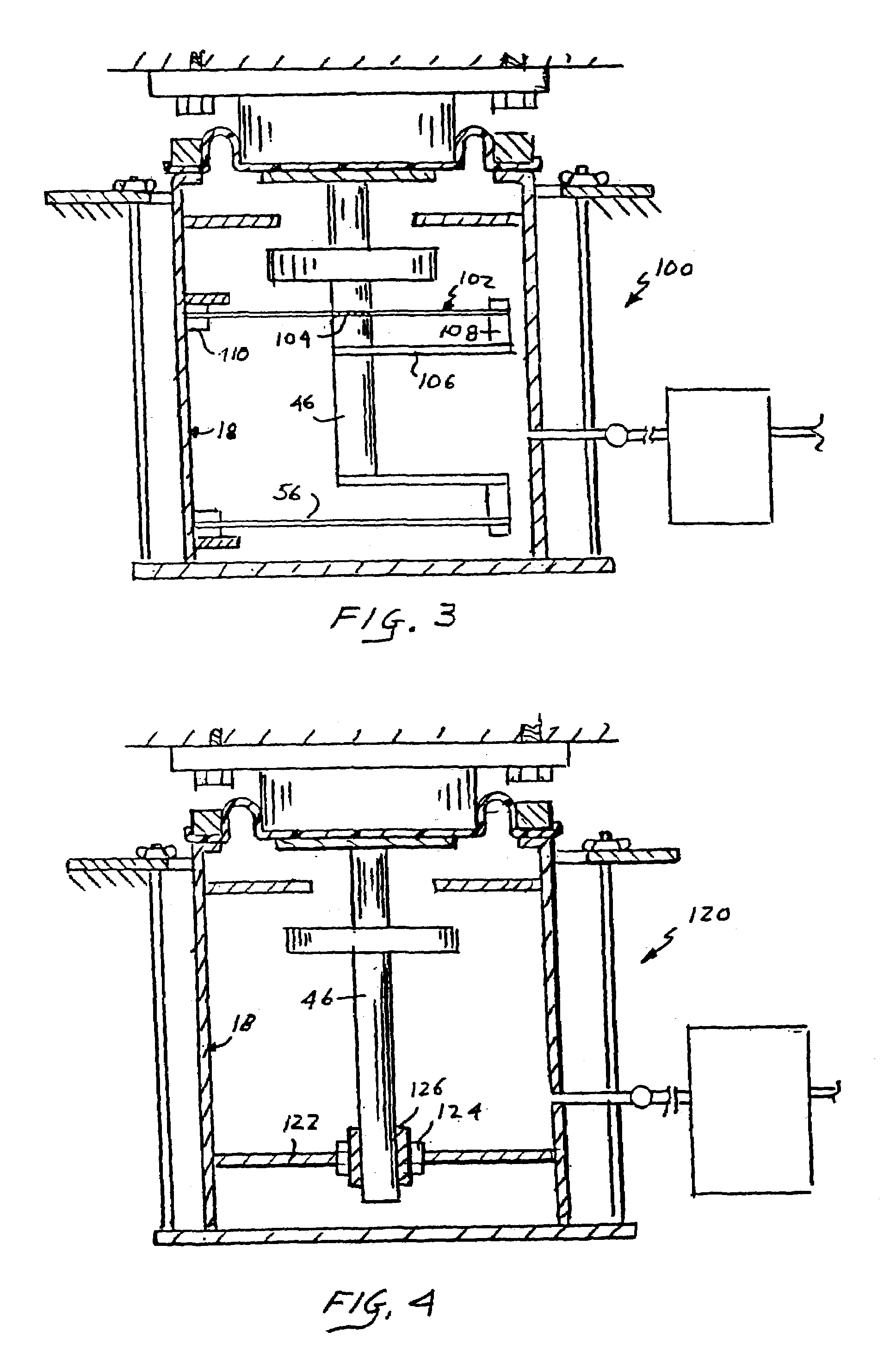
[0019]In another alternate embodiment, a rod extends downwardly from the piston and is received in a linear bearing. The bearing is chosen to have extremely low friction, even when under a side-load. In addition, the bearing must be mounted in a bushing which allows the rod to tilt during ‘power-up’ tilting. The radial stiffness of a rolling rubber diaphragm is used to help constrain tilting of the top plate.

Problems solved by technology

Although this increased tilt stiffness degrades the tilt vibration transfer function for a system, tilt noise is known to be small in most environments.
The isolator top plates cannot be made arbitrarily stiff to tilt.
This ‘power-up’ tilt can involve extremely high torques on the isolator top plates.

Method used


Image

  • High center of gravity stable pneumatic isolator
  • High center of gravity stable pneumatic isolator
  • High center of gravity stable pneumatic isolator

Examples


Embodiment Construction

)

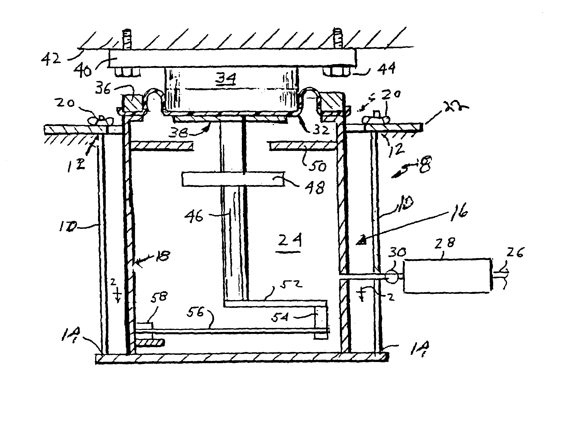
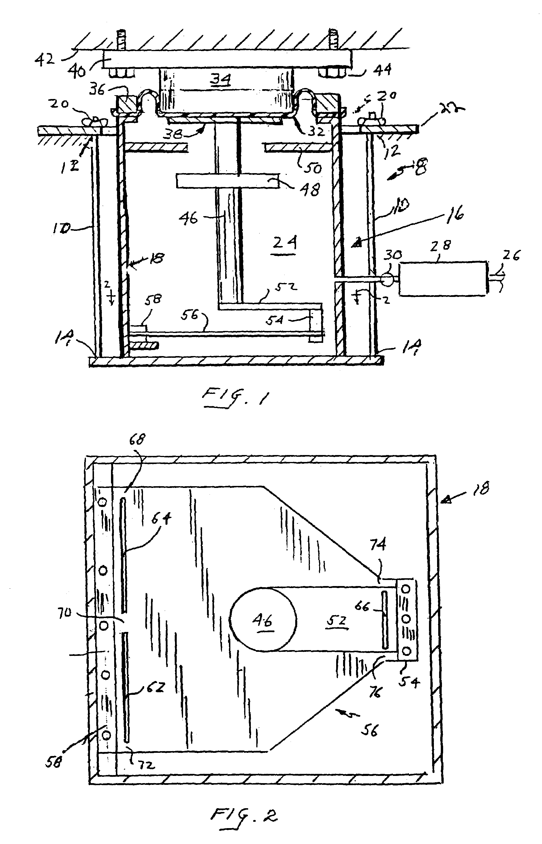
[0026]Referring to FIG. 1, an isolator is shown generally at 8 and comprises three or more wires 10 (only two shown) each having an upper end 12 and a lower end 14. The lower ends, 14 of the wires 10 are flexibly secured to and support a vertical isolator assembly 16 which is comprised of a pressure vessel 18 and a piston 34 flexibly secured to the top of the vessel 18. The upper ends 12 of the wires 10 are flexibly secured to a structure 22 supported by earth. Adjusting screws 20 allow the length of the wires 10 to be adjusted to bring a top plate 40 parallel with the bottom surface of a payload 42. Inside of the vessel 18 is a pressurized volume of air 24. The pressure is controlled by a valving system (not shown) connected at 26. Air from the valving system flows through a second pressure vessel schematically shown at 28 (not to scale), and a flow restricting orifice 30 which together provide vertical damping in the isolator. The air volume of 28 typically has 2–5 times the volu...


PUM


Abstract

A pneumatic isolator for isolating payloads from vibrations consisting of a vertical isolator suspended from pendulum wires. The top load surface of the isolator strongly resists tilt, thus improving payload stability.

Description

[0001]This application is a continuation of application Ser. No. 09 / 836,816, filed Apr. 17, 2001, now abandoned.BACKGROUND OF THE INVENTION[0002]1. Field of Invention[0003]An improved pneumatic vibration isolation system which has additional stability for high center-of-gravity payloads.[0004]2. Description of the Relevant Art[0005]In many sensitive instrumentation applications it is desirable to isolate a payload from ground vibrations. It is well known to integrate a pneumatic air spring with a simple pendulum to isolate from vertical and horizontal ground noise respectively. Air springs have an advantage over conventional springs in that they can maintain a payload at a given operating height independent of changes in the payload's weight. The vibration isolation characteristic of such isolators is also largely independent of the payload's weight. Payloads are generally supported by at least three isolators, with four being the most common number. More isolators can be used to su...

Claims


Application Information

Patent Timeline
Patent Type & Authority Patents(United States)
IPC IPC(8): F16F9/02F16F9/04F16F15/00F16F15/023
CPCF16F15/0232
Inventor NELSON, PETER G.
Owner TECHN MFG
Learn More