
Rolling bearing unit with sensor

a technology of rolling bearing and sensor, which is applied in the direction of solid vibration measurement, metal rolling stand, calender, etc., can solve the problems of troublesome operation to replace the rolling roller, data can be recorded wrong, and labor and time, so as to facilitate further replacement, facilitate the replacement of the member, and enhance the accuracy of temperature and vibration detection of the rolling bearing

Inactive Publication Date: 2005-08-09
NSK LTD
View PDF13 Cites 13 Cited by
  • Summary
  • Abstract
  • Description
  • Claims
  • Application Information

AI Technical Summary

Benefits of technology

The present invention provides a rolling bearing unit with a sensor that can solve the problems of conventional bearing units with sensors. The sensor unit is placed on the axial-direction end portion of the fixed ring or on a separate member that is attached to the fixed ring. The sensor unit can detect temperatures and vibrations of the rolling bearing using a detect part and a memory for recording data. The sensor unit can also transmit the data to an external input / output device using a transmitter device and a receiver device. The sensor unit can be used in a multi-row rolling bearing unit and is particularly useful in a roller neck supporting a rolling roller in a rolling mill. The sensor unit provides accurate detection of abnormal conditions in the rolling bearing and facilitates the replacement of the member for fitting and fixing the outer ring or inner ring and the rolling bearing. The sensor unit can also record data into the memory using the input portion of the external input / output device, which makes it easy to record data during assembly.

Problems solved by technology

For example, in the case of a rolling bearing to be used in the rotation support part of a machine which, in case where a large load is applied thereto to thereby damage its bearing unexpectedly, requires a great deal of labor and time to recover the damaged bearing such as a rolling bearing for supporting a roller neck for supporting the rolling roller of a rolling mill for iron and steel, it is necessary to prevent such unexpected damage of the bearing.
(1) Since the sensors mounted on the housing are connected to the output apparatus by wires such as a harness, when replacing the rolling roller which needs to be replaced relatively frequently, the harness provides an obstacle, so that the operation to replace the rolling roller becomes troublesome.
This can raise a possibility that the data can be recorded wrong.
However, it is troublesome to record the data while paying attention so as not to record the data wrong.

Method used


Image

  • Rolling bearing unit with sensor
  • Rolling bearing unit with sensor
  • Rolling bearing unit with sensor

Examples


first embodiment

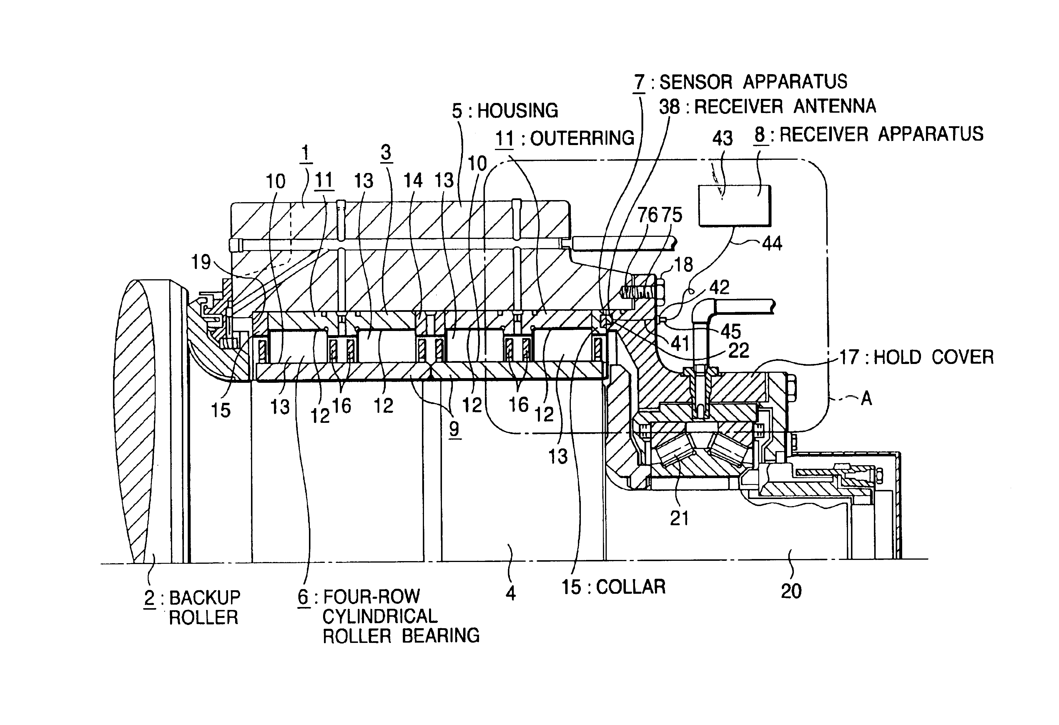
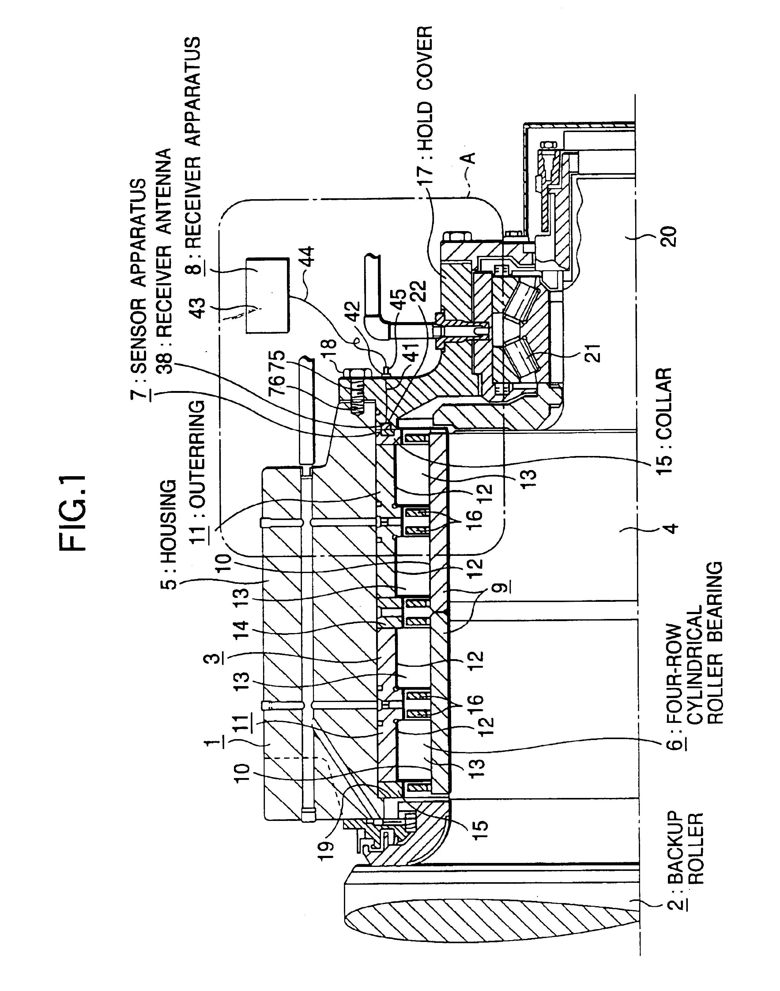
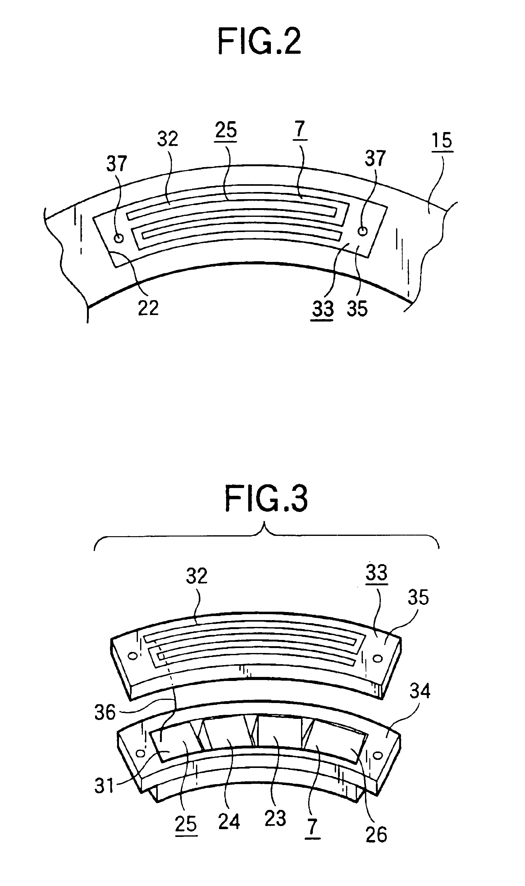
[0036]FIGS. 1 to 5 show a rolling bearing unit with a sensor according to the invention, corresponding to a second aspect of the invention. In this embodiment, a rolling bearing unit with a sensor is incorporated into rotation support portions formed in the axial-direction two end portions of a backup roller 2 disposed in a rolling mill 1 which is used to roll metal material such as iron and steel. That is, a roller neck 4, which is disposed in the central portion between the axial-direction two end faces of the backup roller 2, is rotatably supported inside a housing 4, which does not rotate even when it is in use, by a four-row cylindrical roller bearing 6. And, the four-row cylindrical roller bearing 6, a sensor unit 7 and a receiver apparatus 8 cooperate together in constituting the present bearing unit 3 with a sensor. Of these three elements, the four-row cylindrical roller bearing 6 comprises a plurality of cylindrical rollers 13, 13 respectively between inner raceways 10, 10...

second embodiment

[0045]Next, FIG. 7 shows a rolling bearing unit with a sensor according to the invention, also corresponding to a second aspect of the invention. In the present embodiment, in the diameter-direction middle portion of the axial-direction inner surface (in FIG. 7, the front side surface) of the hold cover 17, there is disposed a substantially-circular-ring-shaped receiver antenna 38a in such a manner that it is concentric with the hold cover 17. And, a portion of the receiver antenna 38a in the circumferential direction thereof is disposed opposed to the sensor unit 7 (see FIGS. 1 and 2) which is disposed on the above-mentioned one collar 15. In the thus structured present embodiment, when it is in use, even in case the above-mentioned one collar 15 is rotated with respect to the hold cover 17, the sensor unit 7 disposed on the above one collar 15 can be disposed opposed to a portion of the receive antenna 38a, so that radio signals transmitted from the sensor unit 7 can be received w...

third embodiment

[0047]Next, FIG. 8 shows a rolling bearing unit with a sensor according to the invention, also corresponding to the second aspect of the invention. In the case of a rolling bearing unit 3 with a sensor according to the present embodiment, the roller neck 47 of a work roller 46 is supported so as to be rotatable with respect to a housing 48. Also, the present rolling bearing unit with a sensor 3 includes a four-row conical roller bearing 49. This four-row conical roller bearing 49 comprises a plurality of cylindrical rollers 54, 54 interposed between inner raceways 51, 51 formed in the outer peripheral surfaces of a pair of inner rings 50, 50 fitted with and fixed to the outer surface of the roller neck 47 of the work roller 46 and a plurality of outer raceways 53, 53 formed in the inner peripheral surfaces of a pair of three outer rings 52a, 52b fitted with and fixed to the inner surface of the housing 5. Also, not only a hold cover 17 is fixed to the axial-direction outer end porti...


PUM

PropertyMeasurementUnit
temperatureaaaaaaaaaa
temperaturesaaaaaaaaaa
rotationaaaaaaaaaa

Abstract

A four-row cylindrical roller bearing is incorporated into between the inner peripheral surface of a housing and the outer peripheral surface of a backup roller. A sensor unit 7 is held in a portion of a collar disposed in the axial-direction end portion of the four-row cylindrical roller bearing. The sensor unit comprises a detect part for detecting temperatures and vibrations and a transmitter device for transmitting signals, which are obtained after output signals taken out from the detect part are processed, as radio signals. On a portion of a hold cover which is a separate member from the collar, there is disposed a receive antenna which is part of a receiver apparatus for receiving the radio signals transmitted by the transmitter device.

Description

BACKGROUND OF THE INVENTION[0001]The present invention relates to a rolling bearing unit with a sensor for use in the rotation support part of a machine which, when a large load is applied thereto to thereby damage the bearing thereof suddenly, requires a lot of labor and time to replace the damaged bearing with a new one, or for use in the rotation support part of a large-sized machine which includes a large number of rotation support parts and thus needs to control the starting times of use of the respective bearings, such as the rotation support part of a rolling roller used in a rolling mill for iron and steel or the rotation support part of various rollers used in a paper manufacturing machine.[0002]For example, in the case of a rolling bearing to be used in the rotation support part of a machine which, in case where a large load is applied thereto to thereby damage its bearing unexpectedly, requires a great deal of labor and time to recover the damaged bearing such as a rollin...

Claims


Application Information

Patent Timeline
Patent Type & Authority Patents(United States)
IPC IPC(8): B21B31/07B21B31/00B61K9/00B61K9/04D21G1/00D21G1/02F16C19/54F16C19/52F16C13/02F16C19/00G01K1/14G01H1/00G01K13/00G01K13/08B21B38/00B21B33/00F16C41/00F16C19/38G01M13/04G01P3/44
CPCD21G1/0226F16C13/02F16C19/28F16C19/388F16C19/525F16C19/527F16C19/54F16C41/008G01H1/003G01K1/024G01K3/005G01K13/08G01M13/04G01M13/045G01P3/443B21B31/07B61K9/04D21G1/008B21B33/00B21B38/006B21B38/008F16C2322/12F16C2233/00
Inventor SATO, YUKIOENDO, SHIGERU
Owner NSK LTD
Learn More