
Tool for chip removing machining and rotatable cutting insert for such tools

a technology of cutting insert and chip removal, which is applied in the field of tools, can solve the problems of unreliable, complicated and unreliable control of cutting insert and keeping, and use of complicated, expensive and unreliable bearing means for cutting inserts

Inactive Publication Date: 2005-08-09
SANDVIK INTELLECTUAL PROPERTY AB
View PDF13 Cites 34 Cited by
  • Summary
  • Abstract
  • Description
  • Claims
  • Application Information

AI Technical Summary

Benefits of technology

The solution enables reliable and simple mounting and dismounting of cutting inserts, maintaining exact position in three orthogonal directions, even under external forces, with minimal lubrication required, allowing for efficient machining of metal workpieces and other materials.

Problems solved by technology

Common for these known tools is, however, that the means for controlling the cutting insert and keeping the same in place in the desired position during rotation are complicated and unreliable in so far that several factors may contribute to the cutting inserts loosing the desired, exact geometrical position thereof in relation to the insert seat of the basic body.
Already the fact that the pin constitutes a separate element, which has to be fitted into holes in the basic body, may give rise to dimensional deviations that counteract exact determination of the position of the cutting insert (e.g. by the pin being deflected under the load of the cutting insert).
The tools that are illustrated in the other three patent publications make use of complicated, expensive and unreliable bearing means for the cutting inserts.
U.S. Pat. No. 5,014,581 and U.S. Pat. No. 5,478,175, it is implied that the cutting insert is manufactured with a long narrow, shaft-like bottom portion; something which makes the cutting insert voluminous and to a large extent limits the possibilities of applying many cutting inserts to one and the same basic body.

Method used


Image

  • Tool for chip removing machining and rotatable cutting insert for such tools
  • Tool for chip removing machining and rotatable cutting insert for such tools
  • Tool for chip removing machining and rotatable cutting insert for such tools

Examples


Embodiment Construction

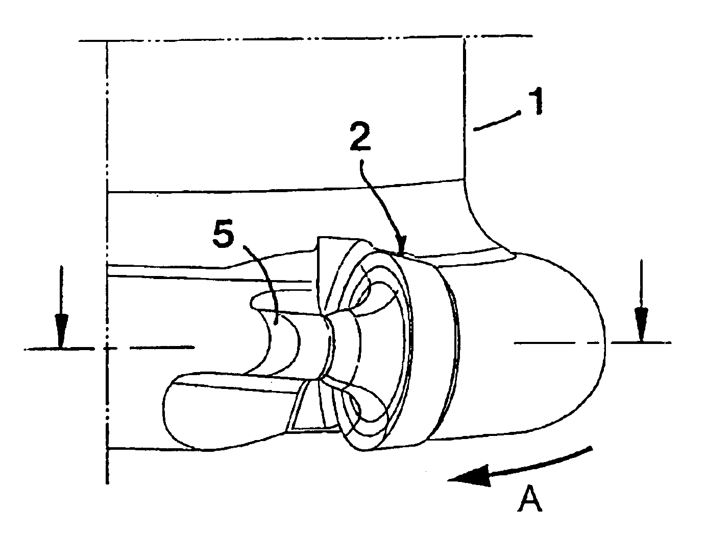
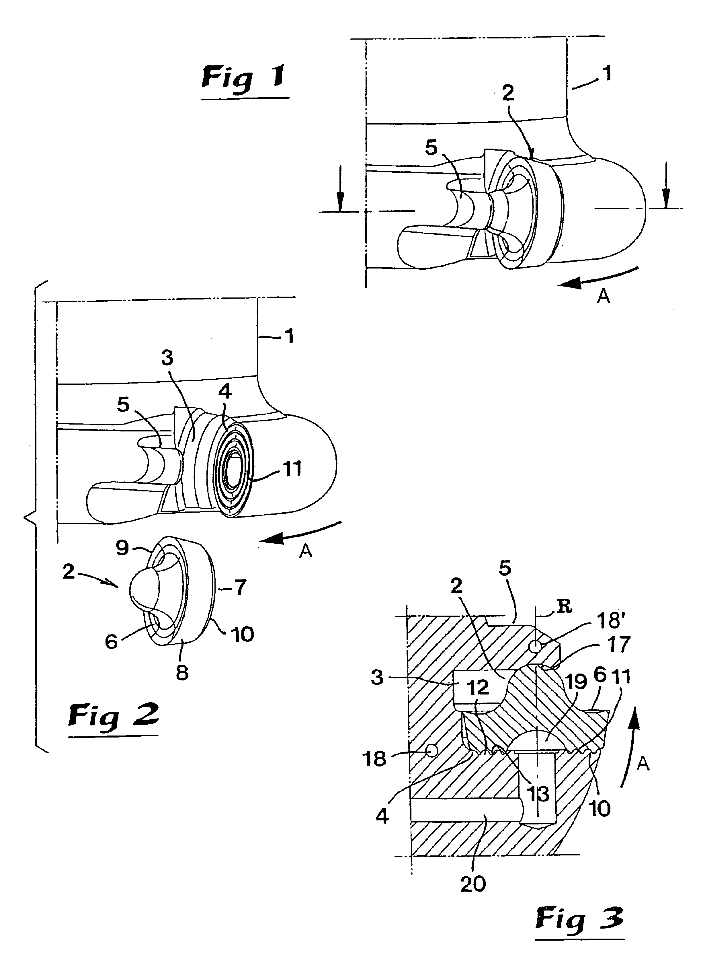
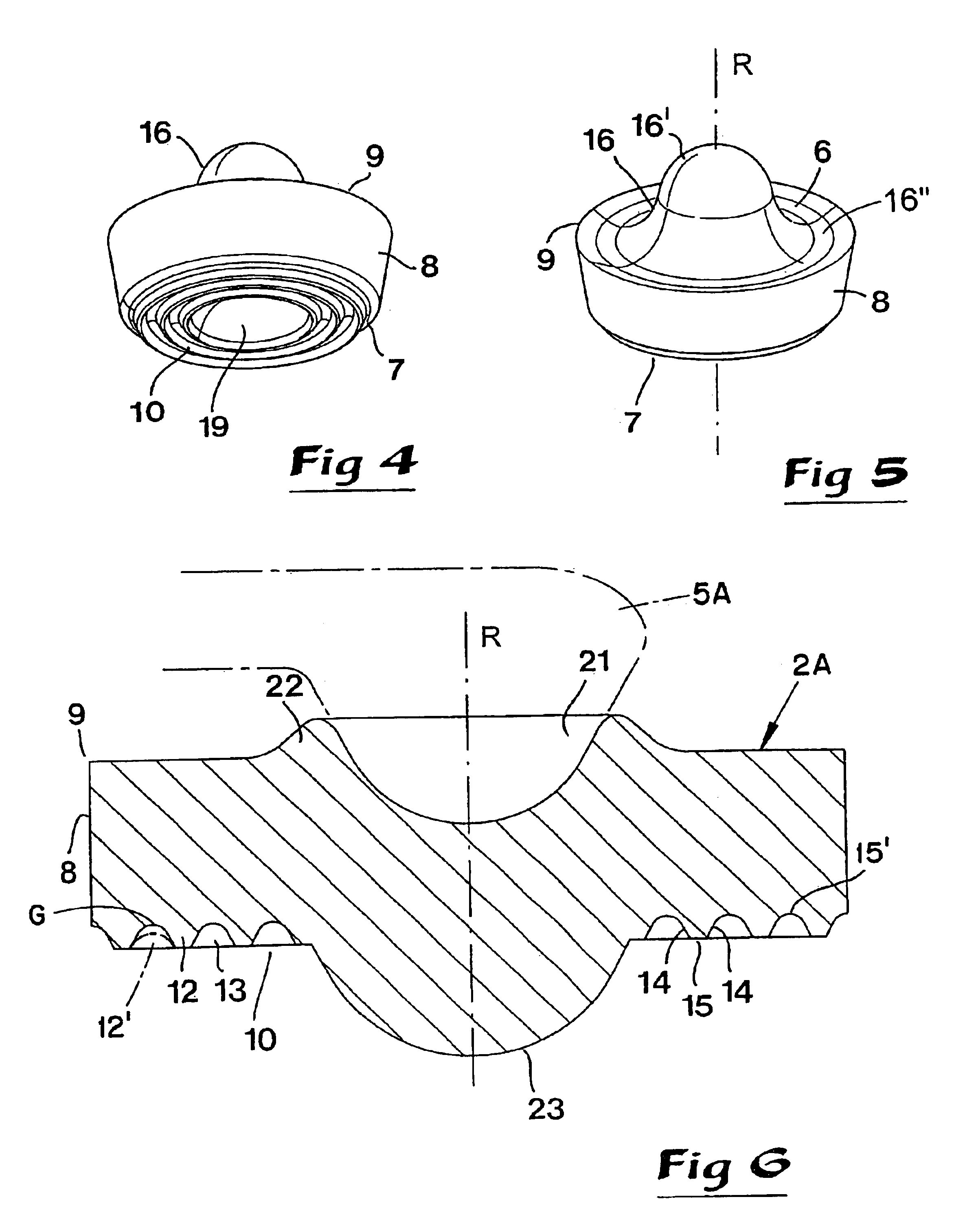
[0018]In FIGS. 1-5, numeral 1 generally designates a basic body of a holder and numeral 2 a rotatable cutting insert. The basic body and the cutting insert together form a tool for chip removing machining, suitably in workpieces of metal. The invention is applicable not only to rotatable tools, such as milling and drilling tools, but also to fixed tools, such as turning tools. In FIGS. 1-3, only one cutting insert is shown on the partially illustrated basic body of the tool. However, in practice, one and the same basic body may be equipped with a plurality of cutting inserts.

[0019]In the practical realization of the invention, the basic body may advantageously, though not necessarily, be manufactured from steel or other comparatively “soft” metal, while the cutting insert is made from a considerably harder and more wear-resistant material, such as conventional cemented carbide, ceramics or the like. In a particularly preferred embodiment, the basic body is made from steel, while the...


PUM

PropertyMeasurementUnit
acute angleaaaaaaaaaa
diametersaaaaaaaaaa
ridge structureaaaaaaaaaa

Abstract

A cutting tool includes a basic body having a insert seat and a rotatable cutting insert mounted on a connecting surface of the seat. The insert includes a chip cutting top side, a bottom side and an outer peripheral side, whereby there is a cutting edge in the area between the top side and the peripheral side. Formed on the connecting surface of the seat is at least one first ring formation, and formed in the bottom surface of the insert is at least one second ring formation having an equal diameter as the first ring formation. At least one of the first and second ring formations comprises a groove. The first and second ring formations are in direct or indirect engagement with each other in order to form a guide between the cutting insert and the basic body that permits rotation of the cutting insert about its own center axis and simultaneously keeps the insert in an exactly defined radial position.

Description

[0001]This application claims priority under 35 U.S.C. §119 to Patent application Ser. No. 0200866-2 filed in Sweden on Mar. 21, 2002, the entire content of which is hereby incorporated by reference.TECHNICAL FIELD OF THE INVENTION[0002]In a first aspect, this invention relates to a tool, intended for chip removing or chip forming machining of the type that comprises on the one hand a basic body having at least one insert seat, and on the other hand a rotatable cutting insert applicable in the same, which is intended to rotate around its own central geometric axis, and which includes a chip cutting top side, a bottom side, and a side surface, whereby there is a cutting edge in the area between the top side and the side surface.[0003]Cutting tools of the type in question are primarily suitable for machining workpieces of metal, although they may also be used for other materials.PRIOR ART[0004]Cutting tools having rotatable cutting inserts of the type generally mentioned above are pre...

Claims


Application Information

Patent Timeline
Patent Type & Authority Patents(United States)
IPC IPC(8): B23C5/20B23C5/16B23C5/22B23B27/12
CPCB23B27/12B23C5/202B23C5/2243B23C2200/081Y10T407/2288Y10T407/23Y10T407/2252Y10T407/192B23C2200/165
Inventor ARVIDSSON, PEDER
Owner SANDVIK INTELLECTUAL PROPERTY AB
Learn More