Mounting apparatus for a transportation system

a transportation system and functional unit technology, applied in the direction of transportation items, loading/unloading vehicle arrangment, load accommodation, etc., can solve the problems of requiring substantial structural alterations, affecting the usability of the region around these freight items, and affecting the usability of the standard aircraft cargo hold, so as to enhance the usability and increase the versatility. the effect of the versatility

Inactive Publication Date: 2005-08-09
TELAIR INTERNATIONAL GMBH
View PDF17 Cites 23 Cited by
  • Summary
  • Abstract
  • Description
  • Claims
  • Application Information

AI Technical Summary

Benefits of technology

[0010]It is an object of the present invention to provide a mounting apparatus that enables an increased versatility of the currently available retaining devices during fixation, and hence enhances the usability of a standard aircraft cargo hold.

Problems solved by technology

In the case of heavy loads, such as engine pallets, this operation can take up to several hours for each pallet.
Furthermore, the region around these freight items (which in such cases are most often pallets) is no longer usable because it is occupied by the retaining belts, which run downward at an angle.
A major problem here is that although adapters and structures especially designed for retaining such equipment could be installed in the floor of the cargo hold, this would require substantial structural alterations and be enormously expensive.
However, such a system causes a blockage in the region around the freight items that are to be secured, so that on one hand the space next to the region into which such an item is loaded cannot be used for anything else, and furthermore the “spider-web system” must be disassembled in order to fill or empty the remaining storage space in the aircraft.
For the above reasons, i.e. in particular for reasons of the limitations on installation of retaining devices imposed by the builders of the aircraft, the fixation of freight items in these regions, in particular along the center line, is necessarily uneconomical.

Method used


Image

  • Mounting apparatus for a transportation system
  • Mounting apparatus for a transportation system

Examples


Embodiment Construction

[0026]In the following description, the same reference numerals are used for identical parts or parts with identical actions.

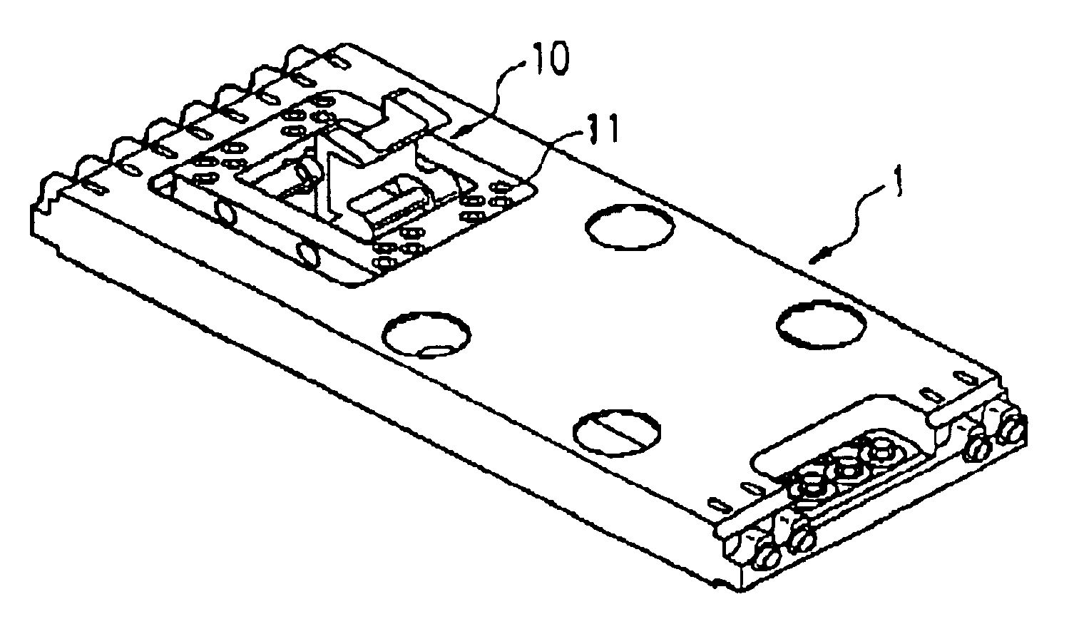
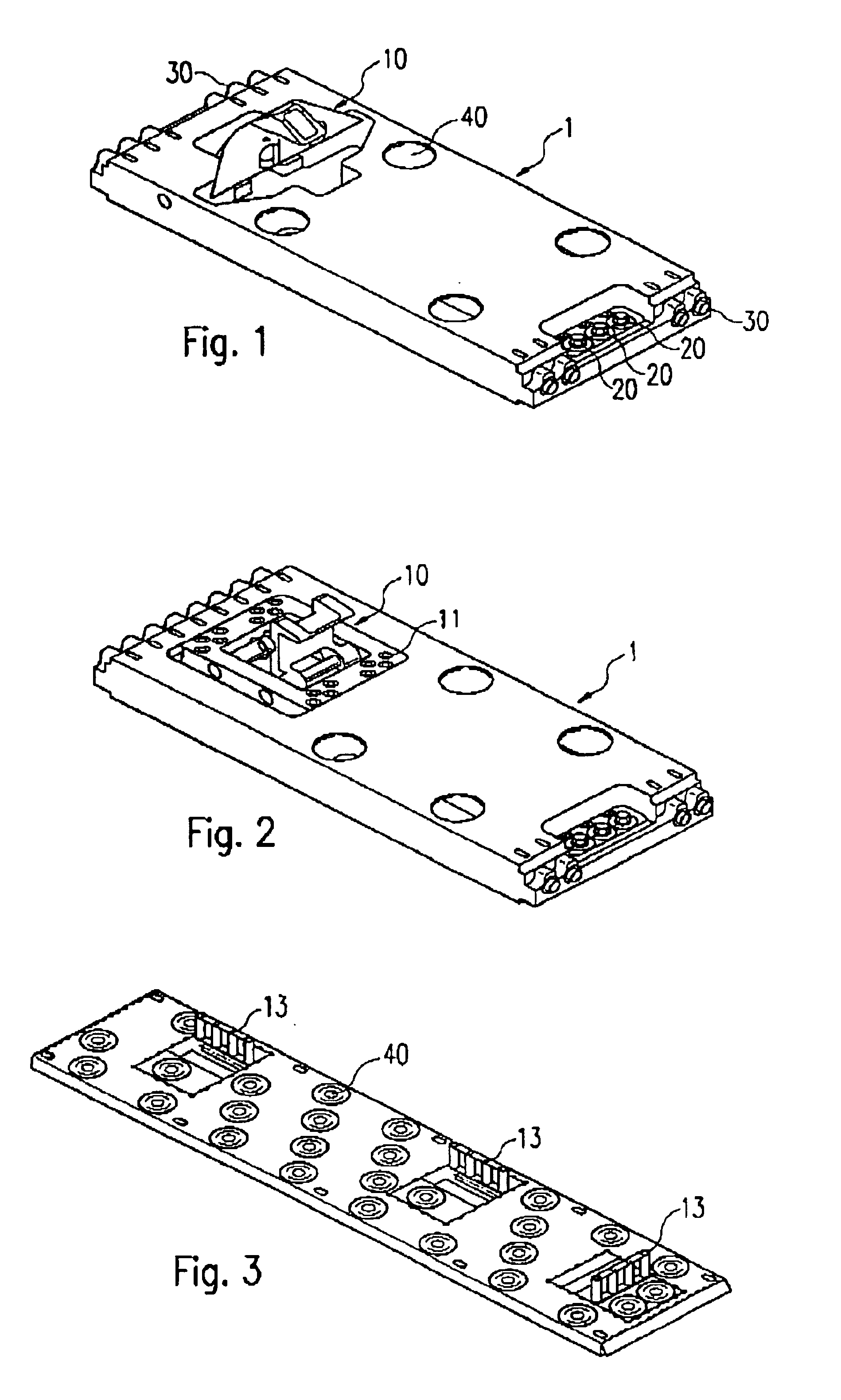
[0027]As shown in FIG. 1, the mounting apparatus comprises a support base 1, which is constructed as a substantially rectangular plate. In the support base 1 is disposed a functional unit 10 of a transportation system, which in the example shown in FIG. 1 is a latch with a lug that can be swiveled away (when contacted by an object approaching from the side). Such latches are generally known.

[0028]On one of its narrow sides first fixation devices 20 are provided, namely bolts that can be anchored in seat rails, such as are known from patent DE 195 25 392 A1. On the opposite side are disposed two fixation devices 30 that can be engaged by insertion into bores within so-called lock trays, which are customarily used on the floor of cargo aircraft for the mounting of power drive units, latch units or other functional units. The said bores are disposed on the side f...


PUM


Abstract

Various kinds of apparatus are known for mounting functional units of conveyor systems, in particular latch units, which can be installed on the floor of a cargo hold in an aircraft. They are provided with detachable fixation devices to fix the functional units to retaining devices attached to the floor, such as seat rails or lock trays. In order to make better use of a cargo hold without the need for installing special fixation devices on its floor, it is proposed to equip the mounting apparatus with a support base that comprises, on opposite sides thereof, different fixation devices, a first of which can be fixed to a first kind of retaining device, such as a seat rail, while simultaneously a second fixation device can be fixed to a second kind of retaining device, such as a lock tray.

Description

RELATED U.S. APPLICATIONS[0001]Not Applicable.STATEMENT REGARDING FEDERALLY SPONSORED RESEARCH OR DEVELOPMENT[0002]Not Applicable.REFERENCE TO MICROFICHE APPENDIX[0003]Not Applicable.FIELD OF THE INVENTION[0004]The invention relates to a mounting apparatus for functional unit of a transportation system such as a latch unit, a guide means or a conveyor means, that can be attached to a floor of a cargo hold in an aircraft.BACKGROUND OF THE INVENTION[0005]Cargo aircraft customarily load items of freight in “single row”, “side by side” or “triple row” configuration. That is, the freight items are stored next to one another in arrays oriented in the long direction of the cargo hold within the aircraft fuselage, such that the arrays can comprise one, two or three rows. There are also variants of this scheme, in particular “multiple choice systems” that allow two or three combinations simultaneously. The single-row array is customarily always disposed down the middle along the center line ...

Claims


Application Information

Patent Timeline
Patent Type & Authority Patents(United States)
IPC IPC(8): B64C1/00B64C1/20B64D9/00
CPCB64C1/20B64D9/003
Inventor HUBER, THOMAS
Owner TELAIR INTERNATIONAL GMBH
Why Eureka
Try Eureka