Threaded fastener for use within multiple substrates

a technology of threaded fasteners and substrates, which is applied in the direction of threaded fasteners, fastening means, screws, etc., can solve the problems of unsuitable threaded screw fasteners, unique adaptation, and insufficient structure for use in connection with the above-mentioned multiplicity, so as to reduce the torque insertion requirements, enhance the insertion speed, and improve the pull-out resistance properties

Inactive Publication Date: 2005-08-09
ILLINOIS TOOL WORKS INC
View PDF13 Cites 54 Cited by
  • Summary
  • Abstract
  • Description
  • Claims
  • Application Information

AI Technical Summary

Benefits of technology

[0011]Another object of the present invention is to provide a new and improved threaded fastener which effectively overcomes the various disadvantages and drawbacks characteristic of PRIOR ART threaded fasteners.
[0014]A last object of the present invention is to provide a new and improved threaded fastener which has new and improved cutting structure integrally incorporated within the peripheral crest regions of the leading threads such that the new and improved threaded fastener is uniquely adapted for abrading, removing, and dispersing material from the particular substrate during the performance of a thread tapping operation such that torque insertion requirements are diminished, insertion speed is enhanced, and pull-out resistance properties are improved.SUMMARY OF THE INVENTION
[0015]The foregoing and other objectives are achieved in accordance with the teachings and principles of the present invention as a result of the provision of a new and improved threaded fastener which comprises a shank portion, a pointed tip portion, and a head portion. The shank portion has a single, substantially continuous, helical thread lead integrally formed thereon, and the threads, disposed upon the forward end section of the shank portion, each have serrated or saw-blade type teeth integrally formed within and arrayed along the crest portions of the threads so as to be present throughout substantially the entire circumferential extent of the threads. The saw-blade or serrated teeth each have a substantially trapezoidal configuration, and valley regions, formed between adjacent ones of the serrated teeth, are characterized or defined by means of included angles of 100°. In addition, the threads are also characterized by means of flank angles which are within the range of 40-60°, whereby the threads will effectively exhibit or be characterized by means of a predetermined amount of rigidity. In this manner, the aforenoted composite features characteristic of the threads of the threaded fastener enable the threaded fastener to in fact be inserted, and become securely threadedly engaged, within diverse types of substrates. It is additionally noted that the saw-blade or serrated teeth serve, in effect, to abrade the substrate material so as to form the threads within the side walls of the substrate, as opposed to cutting the threads within the side walls of the substrate material. Still further, the thread structure also serves to remove and disperse the abraded debris such that the following or trailing threads can smoothly and quickly traverse the previously tapped threads. In this manner, the insertion torque level and installation time are substantially reduced, and still further, the fastener exhibits enhanced pull-out resistance values.

Problems solved by technology

More particularly, such conventional PRIOR ART threaded screw fasteners do not comprise the necessary structure which enables or facilitates their use within the aforenoted multiplicity or diverse types of substrates.
In fact, as has been clearly illustrated by means of the particularly aforenoted PRIOR ART patents to Gerhard and Armstrong, such threaded screw fasteners require particular structure, and commercial or industrial tools for operating the same, which will enable their insertion into concrete or aggregate substrates, however, in a converse manner, such threaded screw fasteners, uniquely adapted for insertion within concrete or aggregate substrates, are not properly structured for use in connection with the aforenoted multiplicity or diverse types of substrate materials other than concrete or aggregate.
In connection with the formation of such boss portion, it has been experienced that the presence of the saw-blade type or serrated teeth upon the threads disposed upon the pointed tip or tapered end portion of the threaded screw fastener will sometimes cause unwanted distortion of the boss portion thereby adversely affecting the insertion and pull-out resistance properties of the threaded screw fastener with respect to the thin gauge sheet metal substrate.

Method used


Image

  • Threaded fastener for use within multiple substrates
  • Threaded fastener for use within multiple substrates
  • Threaded fastener for use within multiple substrates

Examples


example 1

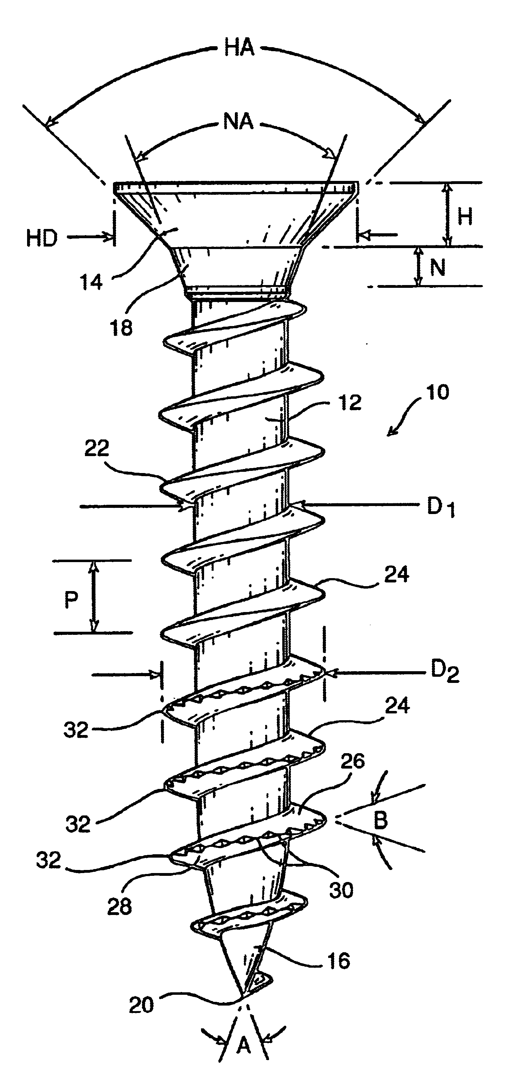
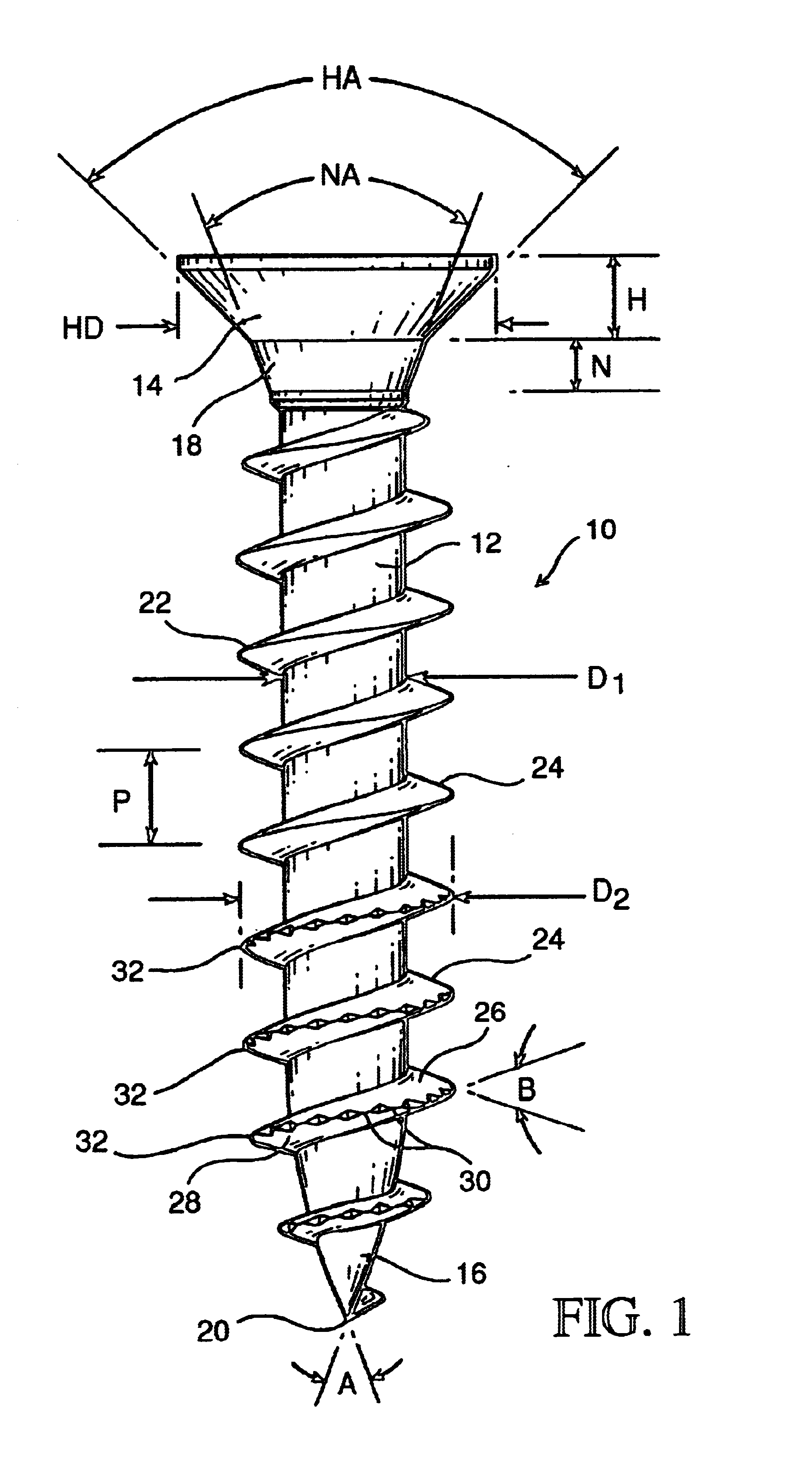
A Number 6 Sized Screw Fastener
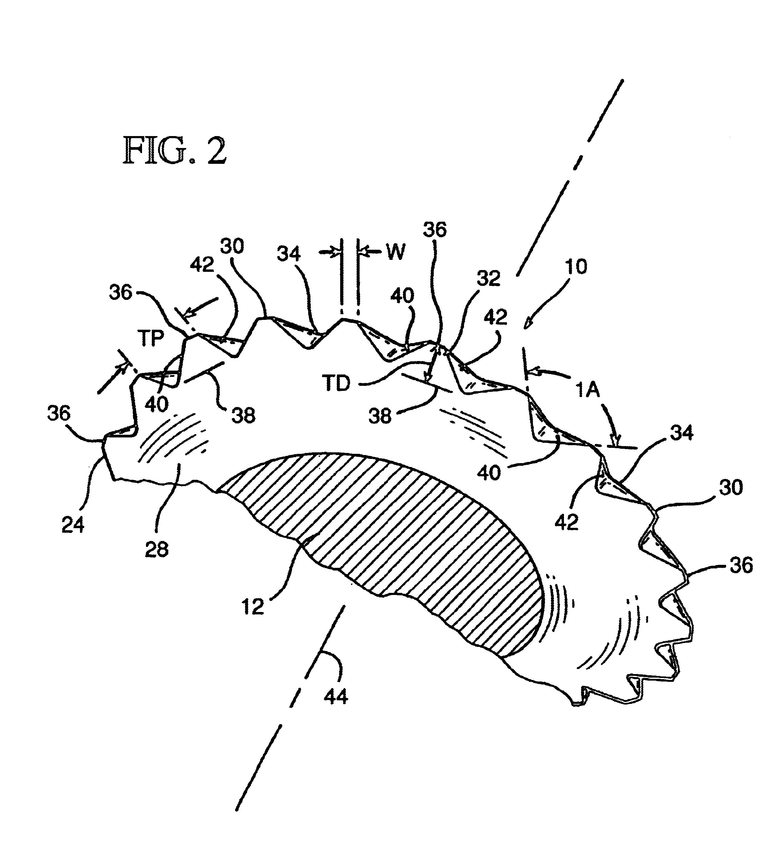
[0030]

Head DiameterHD6.40-6.80 mmHead ThicknessH2.20 mmNeck ThicknessN1.40 mmShank DiameterD12.20 mmThread Crest DiameterD23.30-3.60 mmThread PitchP1.80 mmSaw-Blade Teeth PitchTP0.60 mmSaw-Blade Teeth DepthTD0.21 mmSaw-Blade Teeth Included AngleIA100 Degrees

example 2

A Number 8 Sized Screw Fastener

[0031]

Head DiameterHD7.70-8.10 mmHead ThicknessH2.50 mmNeck ThicknessN1.60 mmShank DiameterD12.40 mmThread Crest DiameterD23.80-4.10 mmThread PitchP2.00 mmSaw-Blade Teeth PitchTP0.60 mmSaw-Blade Teeth DepthTD0.21 mmSaw-Blade Teeth Included AngleIA100 Degrees

example 3

A Number 10 Sized Screw Fastener

[0032]

Head DiameterHD9.10-9.50 mmHead ThicknessH2.80 mmNeck ThicknessN1.80 mmShank DiameterD13.03 mmThread Crest DiameterD24.80-5.10 mmThread PitchP2.60 mmSaw-Blade Teeth PitchTP0.70 mmSaw-Blade Teeth DepthTD0.25 mmSaw-Blade Teeth Included AngleIA100 Degrees


PUM


Abstract

A threaded fastener has a substantially single helical thread formed upon a shank portion thereof, and a plurality of substantially saw-blade type or serrated teeth are formed upon crest portions of leading ones of individual thread portions of the helical thread. The threads of the threaded screw fastener are also characterized by means of predetermined flank angles, and such flank angles, in conjunction with the saw-blade type or serrated teeth, permit the threaded screw fastener of the present invention to be utilized within any one of a multiplicity of substrates, such as, for example, wood, metal, thermoplastics, composite materials, concrete, hard aggregate, or the like.

Description

CROSS REFERENCE TO RELATED PATENT APPLICATION[0001]This patent application is a Continuation-in-Part of U.S. patent application Ser. No. 09 / 918,656 filed on Jul. 31, 2001, now abandoned, in the name of Guenther Reinhard Kram et al. and entitled MULTI-MATE FASTENER.FIELD OF THE INVENTION[0002]The present invention relates generally to threaded fasteners, and more particularly to a new and improved threaded fastener which has a thread lead extending substantially from the headed region of the threaded fastener to the tapered tip region of the threaded fastener, wherein the individual threads of the thread lead are characterized by means of a predetermined flank angle, and wherein further, uniquely configured saw-tooth or serrated-teeth structure is integrally provided upon the peripheral edge regions of the crest portions of those threads which are disposed within the vicinity of the tapered tip region of the threaded fastener, whereby the predetermined flank angle of the individual t...

Claims


Application Information

Patent Timeline
Patent Type & Authority Patents(United States)
IPC IPC(8): F16B25/00F16B25/10
CPCF16B25/0031F16B25/0047F16B25/0052F16B25/10
Inventor KRAM, GUENTHER REINHARDCHEN, CHIN-TSAI
Owner ILLINOIS TOOL WORKS INC
Why Eureka
Try Eureka