
Apparatus and method for monitoring of cathode ray tube panel manufacturing to reduce CRT cost and improve performance and yield

a technology of cathode ray tube and monitoring apparatus, which is applied in the direction of optical radiation measurement, instruments, television systems, etc., can solve the problems of repeated movements and tests, system prediction is not acceptable, and the movement of the panel is relatively long

Inactive Publication Date: 2005-08-09
THOMSON LICENSING SA
View PDF1 Cites 0 Cited by
  • Summary
  • Abstract
  • Description
  • Claims
  • Application Information

AI Technical Summary

Benefits of technology

The invention is a device and process for measuring the brightness of a faceplate panel used in the production of a CRT. The device includes a top plate with detectors for measuring light output, a bottom plate with light outputs that oppose the detectors, and a computer for controlling the light source and recording data. The method involves accurately positioning the faceplate panel between the plates and controlling the light sources to measure the brightness of the panel. The device allows for precise monitoring of the brightness of the faceplate panel, which improves the quality of the finished CRT.

Problems solved by technology

This system has been found to be unacceptable in predicting resultant light output gradient in a finished CRT.
A problem with such a system is that the panel movement takes a relatively long time and repetitive movements and tests are required in multiple passes.
This lowers the production rate to a point where it may be impossible to meet a particular desired inspection time, e.g., 12 seconds per panel.
Another problem with this system is that invalid readings can be processed, which can result in the acceptance of an out-of-tolerance panel.

Method used


Image

  • Apparatus and method for monitoring of cathode ray tube panel manufacturing to reduce CRT cost and improve performance and yield
  • Apparatus and method for monitoring of cathode ray tube panel manufacturing to reduce CRT cost and improve performance and yield
  • Apparatus and method for monitoring of cathode ray tube panel manufacturing to reduce CRT cost and improve performance and yield

Examples


Embodiment Construction

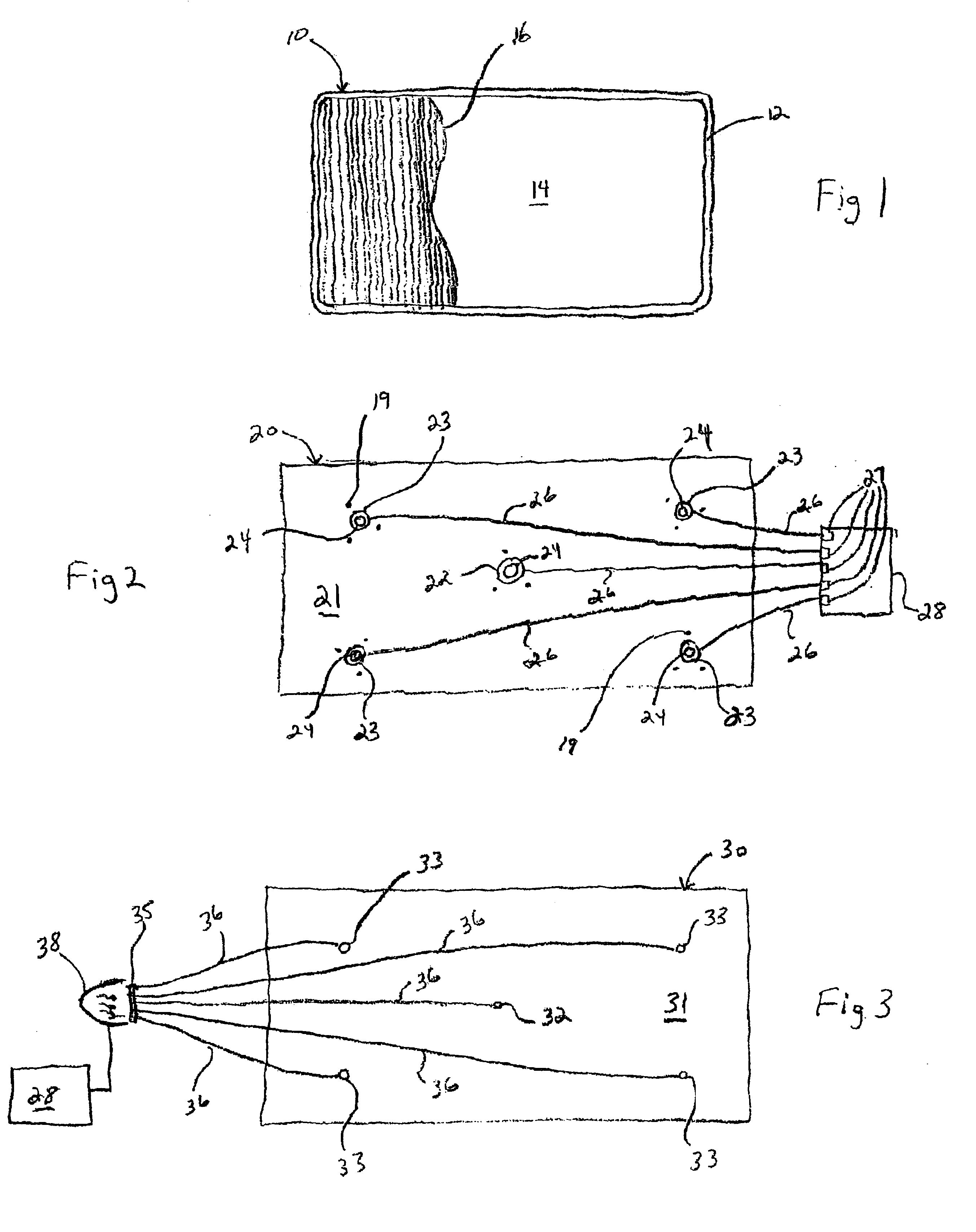
[0012]The monitoring apparatus 18 of the present invention will now be described in greater detail with reference to FIGS. 1-5. Referring first to FIG. 1, a faceplate panel 10 for use in a cathode ray tube (CRT) is shown. The faceplate panel 10 consists of a front face 14 surrounded by a plurality of side walls 12. The side walls 12 extend generally orthogonal to the front face 14. The side walls 12 are generally attached to funnel forming a tube having an electron gun at an opposite end facing the faceplate panel 10. A matrix 16 is applied to the inner surface of the front face 14. The matrix 16 consists of a plurality of parallel lines which extend vertically across the entire inner surface of the front face 14.

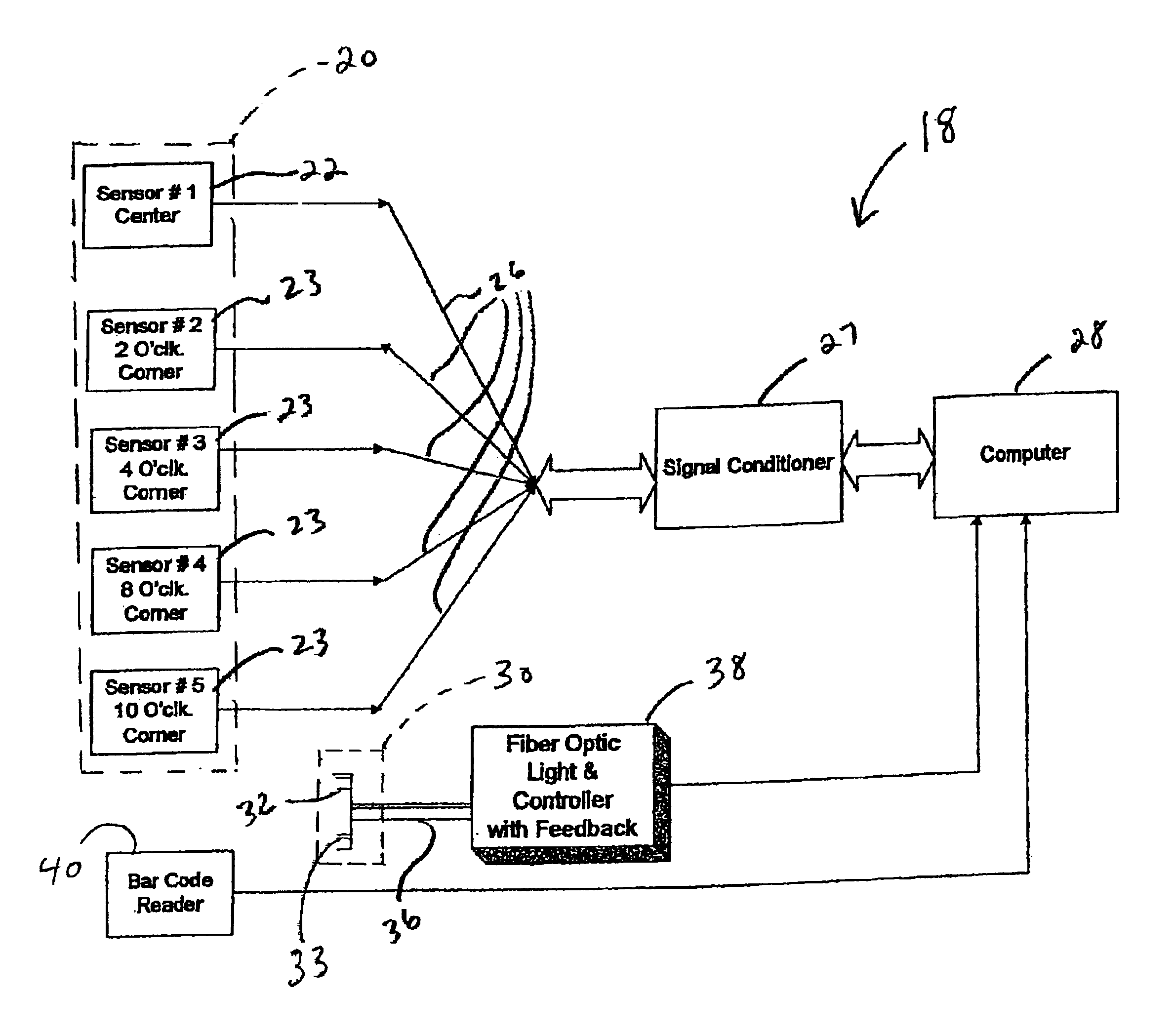
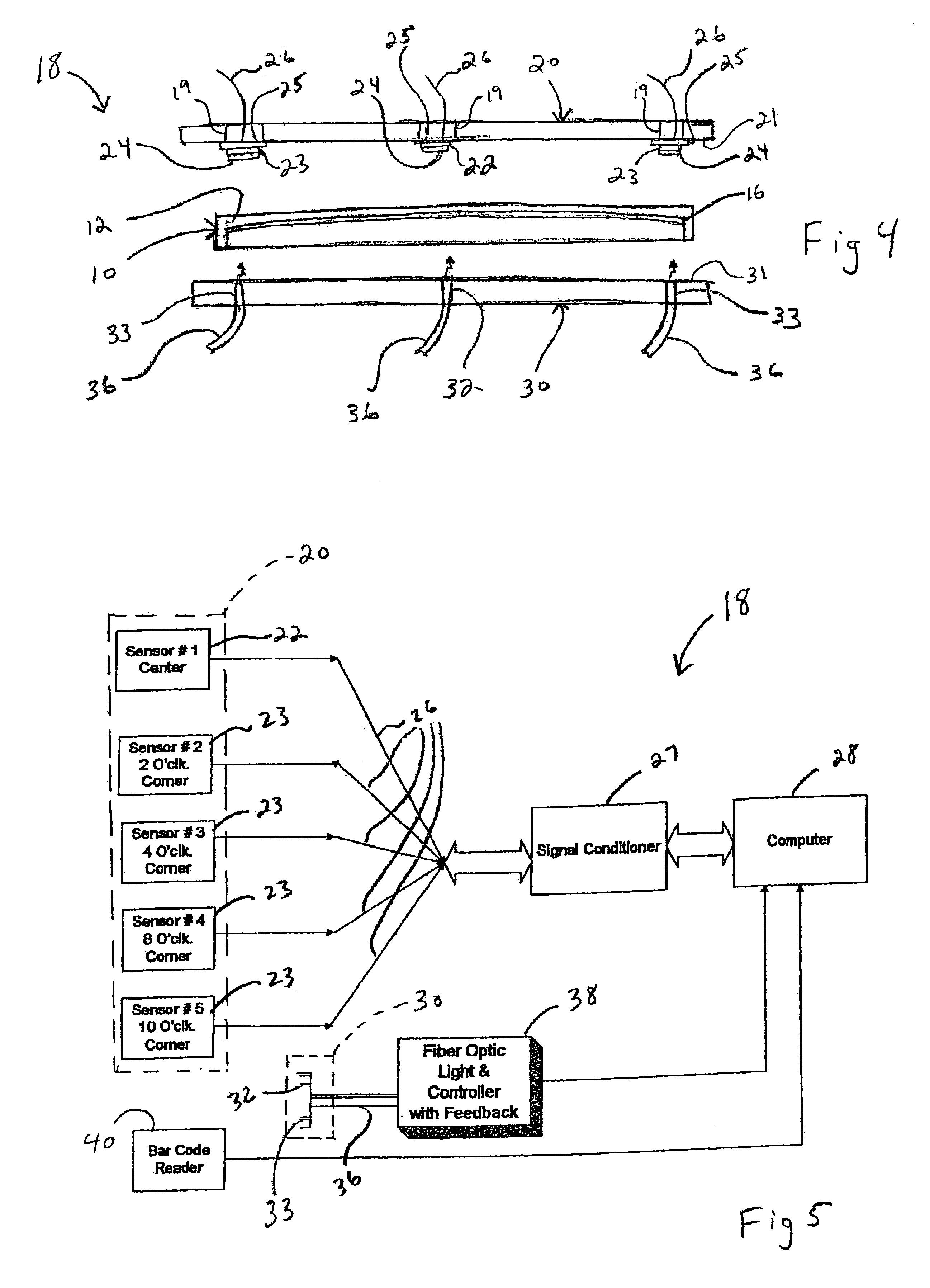
[0013]Turning now to FIGS. 4 and 5, the monitoring apparatus 18 is shown. The monitoring apparatus 18 consists generally of a computer 28, a signal conditioner 27, a light source 38, a bar code reader 40, a top plate 20 having a plurality of sensors and a bottom plate 30 ha...


PUM

PropertyMeasurementUnit
thresholdaaaaaaaaaa
thicknessaaaaaaaaaa
transparentaaaaaaaaaa

Abstract

A monitoring apparatus and method for measuring light output gradient of a faceplate panel includes a top plate having a center detector and a plurality of corner detectors mounted along a major surface thereof. Lenses are optically coupled to a respective detector, and radiometers are electrically coupled to a respective detector. A bottom plate spaced apart from the top plate has a plurality of light outputs mounted along a major surface thereof and positioned to be opposite each detector. A light source is optically coupled to each light output through a splitter. A computer is electrically coupled to the light source for receiving feedback therefrom and for controlling the light source. The computer is also electrically coupled to each radiometer for recording data therefrom.During monitoring, a faceplate panel having a matrix applied thereto is accurately positioned between the top and bottom plates such that the center detector is located approximately above the center of the faceplate panel. Light is passed from the light sources through the faceplate panel to the detectors under control of the computer. The light output measurements at each detector are recorded by the computer and calculation is made of a light output gradient based upon a comparison of the light output at the center detector to the light output at the corner detector.

Description

FIELD OF THE INVENTION[0001]This invention pertains generally to a method and apparatus for measuring light output through a periodic matrix on a surface and, particularly, to a method and apparatus for measuring such light output on a cathode-ray tube faceplate panel.BACKGROUND OF THE INVENTION[0002]Most cathode ray tubes exhibit a center to edge light output gradient. Typically, the center light output exceeds the corner light output and is the result of a number of contributing factors. For example, the geometry or thickness of the faceplate panel glass along with the absorption characteristics of the glass. Light output gradient is also affected by other processes applied to the inside of the faceplate panel. During production of cathode-ray tubes (CRTs) for color television receivers, a black matrix is applied to the inside surface of the faceplate panel. The black matrix consists of parallel lines which extend vertically as defined by the viewing orientation of a conventional ...

Claims


Application Information

Patent Timeline
Patent Type & Authority Patents(United States)
IPC IPC(8): H01J9/42H01J9/24
CPCH01J9/244H01J9/42
Inventor GOROG, ISTVANVU, TONY TUANBARAN, ANTHONY STANLEY
Owner THOMSON LICENSING SA
Learn More